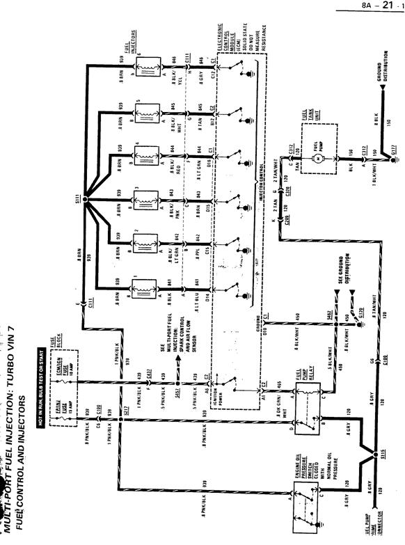
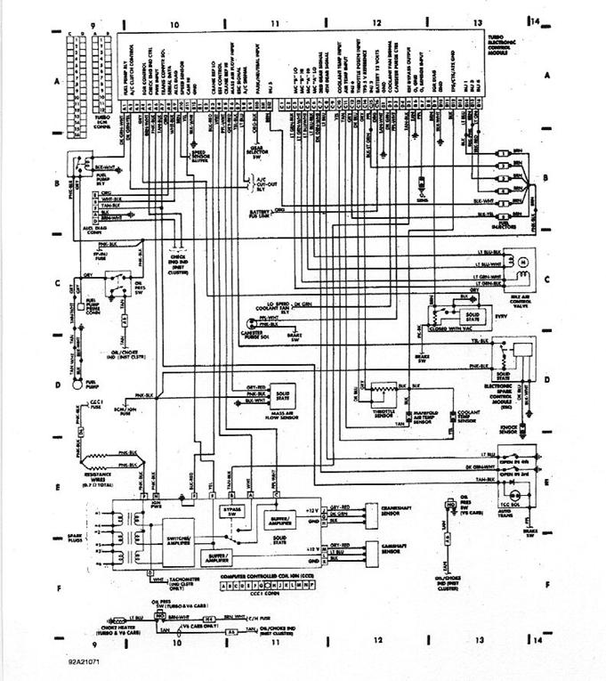
HOT AIR TURBO/SFI
V-6 NOTES
|
84-85 Turbo 3.8 Liter Engine Sensors |

 ECM Harness
1. Electronic Control Module (ECM)
2. Assembly Line Diagnostic Link (ALDL) Connector
3. Service Engine Soon Light
4. ECM +12 Volt Connection
5. ECM Harness Ground
6. Fuse Panel
 Not ECM Connected
7. Fuel Filter
8. Positive Crankcase Ventilation (PCV) Valve
9. N/A
10. Turbocharger
 Controlled Devices
11. Fuel Injectors (6)
12. Idle Air Control (IAC) Motor
13. Fuel Pump Relay
14. Transmission Converter Clutch (TCC) Connector
15. Computer Controlled Coil (C3I) Ignition
16. Electronic Spark Control (ESC) Module
17. Exhaust Gas Recirculation (EGR) Vacuum Solenoid
18. Air Conditioning Compressor Relay
19. Fuel Vapor Canister Solenoid
20. Wastegate Control Solenoid
 Information Sensors
25. Exhaust Oxygen (O2)
26. Throttle Position (TPS)
27. Coolant Temperature
28. Camshaft Position
29. Crankshaft Position
30. Mass Air Flow (MAF)
31. Knock Sensor
32. Transmission Park/Neutral (PN) Switch
33. Vehicle Speed Sensor (VSS)
34. MAP Sensor
The perfect place to add a remote oil pressure sensor is the back of block. Remove the passengers side galley plug (must be passengers side) install fitting and run a hard (pre-made) brake line up through a hole that you will have to drill beside the knock sensor. Then put the oil pressure sensor at the rear of engine.
Type 1
Module is available from GM PartsDirect.com, P/N 24503624 for $154.06.
Coil Pack is available at Summit P/N ACC-140016 for $85.95
|
1984-1985 Turbo Regal Common Parts |
| gnttype-webmaster@gnttype.org |
|
GM and Non-GM Parts |
|
Coil |
25533542 |
|
Coil-to-ignition module gasket |
25526450 |
|
Fuel pressure regulator, Turbo TA and Somerset |
25523720 |
|
Head bolts - torque to yield Long |
25525953 |
|
Short |
25527831 |
|
Ignition Module |
25526449 |
|
Turbo Inlet Gasket - Rivera |
1261269 |
|
Seal adapter to turbo ( o-ring ) |
25515935 |
|
Seal adapter to intake ( o-ring ) |
1262817 |
|
Wastegate - adjustable |
25527603 |
|
Non GM parts |
|
|
Larger rear brake cylinders GM |
18012305 |
|
EIS |
104432 |
|
Bendix |
33892 |
|
Felpro Gaskets Exhaust |
1400 |
|
Felpro Gaskets Intake |
1200 |
|
Felpro Gaskets Heads (4.1) |
1026 |
|
Main seal kit |
BS40613 |
|
Higher Capacity Oil Filters |
|
|
AC |
PF-52 |
|
Fram |
3980 |
|
Bosch O2 Sensors |
0-258-002-019 |
|
Fuel Injector O rings (Also for regulator) |
SK1 RN7 |
|
Remote Oil pressure sending unit (like used on the GNX) Stewart-Warner |
F-279B |
|
Walker Super Turbo DynoMax Mufflers (2 1/4" in/out) |
17731 |
|
K & N Filters Stock Replacement style |
RE-0910 |
|
GM and Non-GM Parts |
DESCRIPTION |
PART NUMBER |
NOTE |
|||||||||||||||||||||||||||||||||||
|
A/C compressor spacer .030" to align pulleys |
14047730 |
. |
|||||||||||||||||||||||||||||||||||
|
AC/Delco Tread Sealer with Teflon |
14011040 |
. |
|||||||||||||||||||||||||||||||||||
|
Bolt, Rod Cap |
25531956 |
. |
|||||||||||||||||||||||||||||||||||
|
Bolt, Main Cap |
25517607 |
. |
|||||||||||||||||||||||||||||||||||
|
Bolt, Head -torque to yield Long |
25525953 |
. |
|||||||||||||||||||||||||||||||||||
|
Bolt, Head-torque to yield Short |
25527831 |
. |
|||||||||||||||||||||||||||||||||||
|
Boost Solenoid |
1997157 |
. |
|||||||||||||||||||||||||||||||||||
|
Brace, Alternator accessory |
25525338 |
Discontinued |
|||||||||||||||||||||||||||||||||||
|
Calpack |
16036503 |
Alternate: 16036504 |
|||||||||||||||||||||||||||||||||||
|
Cam thrust button w/needle bearings |
25532588 |
. |
|||||||||||||||||||||||||||||||||||
|
Cam Sprocket(nylon over teeth) |
25523115 |
|
|||||||||||||||||||||||||||||||||||
|
Coil-to-ignition module screw |
25533541 |
. |
|||||||||||||||||||||||||||||||||||
|
Coil-to-ignition module gasket |
25526450 |
. |
|||||||||||||||||||||||||||||||||||
|
Coolant Temp Switch(on intake under FPR) |
.3053190 |
|
|||||||||||||||||||||||||||||||||||
|
Coolant recovery reservoir |
25525470 |
. |
|||||||||||||||||||||||||||||||||||
|
Crank Shaft, GN/T-Type |
12350247 |
. |
|||||||||||||||||||||||||||||||||||
|
Crank Shaft, Turbo Trans-AM (Same as above but has cross drilled main journals) |
25535742 |
. |
|||||||||||||||||||||||||||||||||||
|
Crankshaft Balancer Spacer "seal" .030" (max. .060") |
25523377 |
. |
|||||||||||||||||||||||||||||||||||
|
Crank Sensor (Complete) |
25525667 |
. |
|||||||||||||||||||||||||||||||||||
|
Crank Sensor Bracket |
12537113 |
(AC/Delco #213-280) |
|||||||||||||||||||||||||||||||||||
|
Crank Sensor Bolt |
12537114 |
(AC/Delco #213-281) |
|||||||||||||||||||||||||||||||||||
|
Crank Sensor |
12537109 |
(AC/Delco #213-292) |
|||||||||||||||||||||||||||||||||||
|
1986 ESC Module |
16022614 |
. |
|||||||||||||||||||||||||||||||||||
|
1987 ESC Module |
16051654 |
. |
|||||||||||||||||||||||||||||||||||
|
Cam Sensor With Drive |
25516915 |
. |
|||||||||||||||||||||||||||||||||||
|
Cam Sensor |
25518357 |
. |
|||||||||||||||||||||||||||||||||||
|
Cam Sensor Shaft O Ring |
1959331 |
. |
|||||||||||||||||||||||||||||||||||
|
Cam Sensor Spacer Shims |
1837617 |
. |
|||||||||||||||||||||||||||||||||||
|
EGR filter |
10159525 |
. |
|||||||||||||||||||||||||||||||||||
|
EGR Valve |
17111570 |
|
|||||||||||||||||||||||||||||||||||
|
ECM |
1227148 |
. |
|||||||||||||||||||||||||||||||||||
|
Engine, Short Block minus cam |
25527476 |
List $1575 on 6-91 Discontinued |
|||||||||||||||||||||||||||||||||||
|
Exhaust Turbo Outlet Pipe (Downpipe) |
25526459 |
. |
|||||||||||||||||||||||||||||||||||
|
Exhaust Catalytic Converter |
25103338 |
. |
|||||||||||||||||||||||||||||||||||
|
Exhaust "Y" Pipe After Converter |
25525383 |
. |
|||||||||||||||||||||||||||||||||||
|
Exhaust Pipe Over Axle LH |
25520013 |
. |
|||||||||||||||||||||||||||||||||||
|
Exhaust Pipe Over Axle RH |
25520012 |
. |
|||||||||||||||||||||||||||||||||||
|
Exhaust Muffler |
25520009 |
. |
|||||||||||||||||||||||||||||||||||
|
Exhaust Tail Pipe LH |
25520011 |
. |
|||||||||||||||||||||||||||||||||||
|
Exhaust Tail Pipe RH |
25520012 |
. |
|||||||||||||||||||||||||||||||||||
|
Exhaust Manifold LH |
25527391 |
. |
|||||||||||||||||||||||||||||||||||
|
Exhaust Manifold RH |
25527378 |
. |
|||||||||||||||||||||||||||||||||||
|
Exhaust, Catalytic Converter Hanger |
25525381 |
. |
|||||||||||||||||||||||||||||||||||
|
Fan delay relay |
25527402 |
. |
|||||||||||||||||||||||||||||||||||
|
Fan Hi and Low Relay |
25526984 |
. |
|||||||||||||||||||||||||||||||||||
|
Passenger Side Relay Shroud |
25518460 |
. |
|||||||||||||||||||||||||||||||||||
|
Flexplate Turbo 81-87 (heavier piston/pins) |
25512350 |
. |
|||||||||||||||||||||||||||||||||||
|
Fuel pressure regulator, Turbo TA and Somerset |
25523720 |
. |
|||||||||||||||||||||||||||||||||||
|
Fuel Rail |
25524302 |
. |
|||||||||||||||||||||||||||||||||||
|
Fuel Rail, Feed Line (Pipe Assembly) |
25526146 |
. |
|||||||||||||||||||||||||||||||||||
|
Fuel Injector O Ring |
10031124 |
. |
|||||||||||||||||||||||||||||||||||
|
Fuel Injector Wire Harness |
12060425 |
. |
|||||||||||||||||||||||||||||||||||
|
Fuel Pump Strainer Sock |
25055458 |
. |
|||||||||||||||||||||||||||||||||||
|
Fuel Line 'O' Rings Return line at FPR . |
22516256 |
|
|||||||||||||||||||||||||||||||||||
|
Fuel Line 'O' Rings Feed line at fuel rail |
22514722 |
|
|||||||||||||||||||||||||||||||||||
|
Fuel Meter Gasket (Between Sender and Tank) |
12337247 |
. |
|||||||||||||||||||||||||||||||||||
|
Fuel Pump Relay |
10038490 |
. |
|||||||||||||||||||||||||||||||||||
|
Fuel Pump Hanger/Sender |
9167390510 |
. |
|||||||||||||||||||||||||||||||||||
|
Gasket Kit, Engine Overhaul (Contains all engine gaskets EXCEPT valve seals) |
12328748 |
. |
|||||||||||||||||||||||||||||||||||
|
Gasket Kit, Top End (Includes head gaskets, intake gasket, and valve cover gaskets) |
12328759 |
. |
|||||||||||||||||||||||||||||||||||
|
Gasket kit, Front cover (Includes cover gasket, water pump gasket, mechenical fuel pump block off plate gasket. This kit will also fit Buick 3.0L FWD V6) |
12337540 |
. |
|||||||||||||||||||||||||||||||||||
|
Gasket, Oil Pan |
25521994 |
. |
|||||||||||||||||||||||||||||||||||
|
Gasket, oil pick up screen to block |
24501259 |
. |
|||||||||||||||||||||||||||||||||||
|
Gasket, Head gaskets (composite) |
25528486 |
. |
|||||||||||||||||||||||||||||||||||
|
Gasket, Head gasket (steel shim) |
25524599 |
. |
|||||||||||||||||||||||||||||||||||
|
Gasket, EGR to intake $1.14 |
25530599 |
. |
|||||||||||||||||||||||||||||||||||
|
Gasket, IAC (round) |
25530697 |
. |
|||||||||||||||||||||||||||||||||||
|
Gasket, Upper Plenum to Intake |
24502089 |
. |
|||||||||||||||||||||||||||||||||||
|
Gasket, Throttle-Body to Upper Plenum |
25517008 |
. |
|||||||||||||||||||||||||||||||||||
|
Gasket, Turbo Inlet bell |
25514608 |
. |
|||||||||||||||||||||||||||||||||||
|
Gasket, Vacuum block (top of throttle body) |
25536028 |
. |
|||||||||||||||||||||||||||||||||||
|
Gas tank, with TR baffle |
22523080 |
. |
|||||||||||||||||||||||||||||||||||
|
Governor (transmission) |
8655976 |
. |
|||||||||||||||||||||||||||||||||||
|
Grommet, Pass Side Valve Cover |
1264486 |
|
|||||||||||||||||||||||||||||||||||
|
Heater hoses Inlet |
25525213 |
. |
|||||||||||||||||||||||||||||||||||
|
Outlet |
25525214 |
. |
|||||||||||||||||||||||||||||||||||
|
To water pump |
25525228 |
. |
|||||||||||||||||||||||||||||||||||
|
Water pump Bypass |
25525245 |
. |
|||||||||||||||||||||||||||||||||||
|
Idle Air Control (IAC) |
25527077 |
|
|||||||||||||||||||||||||||||||||||
|
Ignition module |
25526449 |
. |
|||||||||||||||||||||||||||||||||||
|
Intake Manifold |
25527221 |
. |
|||||||||||||||||||||||||||||||||||
|
Intake, Upper Plenum |
25525146 |
. |
|||||||||||||||||||||||||||||||||||
|
Knock Sensor |
10456287 |
|
|||||||||||||||||||||||||||||||||||
|
Lifter Set |
5234485-12 |
. |
|||||||||||||||||||||||||||||||||||
|
Low fuel warning assembly |
6432974 |
. |
|||||||||||||||||||||||||||||||||||
|
Mass air flow sensor |
25007866 |
Discontinued |
|||||||||||||||||||||||||||||||||||
|
MAF Sensor (3"Impalla SS) |
25180303 |
(AC/Delco 1#213-352) |
|||||||||||||||||||||||||||||||||||
|
Motor Mounts Left |
1255273 |
. |
|||||||||||||||||||||||||||||||||||
|
Right |
1255274 |
. |
|||||||||||||||||||||||||||||||||||
|
Oil Cooler Adapter |
25530885 |
Discontinued |
|||||||||||||||||||||||||||||||||||
|
Oil Cooler Adapter O Ring |
25530999 |
. |
|||||||||||||||||||||||||||||||||||
|
Oil Pressure Switch |
25036378 |
|
|||||||||||||||||||||||||||||||||||
|
Oil Pressure Switch Molded Connector |
12085529 |
(has 3 white wires which need to be spliced in) |
|||||||||||||||||||||||||||||||||||
|
Oil Pump, stock |
12337732 |
. |
|||||||||||||||||||||||||||||||||||
|
Oxygen Sensor, (Stock) |
25162693 |
(AFS-20) |
|||||||||||||||||||||||||||||||||||
|
Oxygen Sensor, (GNX) |
25162753 |
(AFS-22) |
|||||||||||||||||||||||||||||||||||
|
Oxygen Sensor, (GM) Heated |
25312179 |
(AFS-74) |
|||||||||||||||||||||||||||||||||||
|
Oil Supplement, GM Engine (EOS) |
1052367 |
. |
|||||||||||||||||||||||||||||||||||
|
Posi Traction Additive |
1052358 |
. |
|||||||||||||||||||||||||||||||||||
|
Posi, Clutch Pack |
00231127 |
. |
|||||||||||||||||||||||||||||||||||
|
Positive Battery Cable |
12157883 |
. |
|||||||||||||||||||||||||||||||||||
|
PCV valve |
25095468 |
AC# CV893C |
|||||||||||||||||||||||||||||||||||
|
PCV grommet |
1381487 |
. |
|||||||||||||||||||||||||||||||||||
|
PCV hose |
10055808 |
non turbo part that works-must cut to fit |
|||||||||||||||||||||||||||||||||||
|
PCV hose Dayco |
87000 |
3/8" hose with a 90 degree bend that can be trimmed |
|||||||||||||||||||||||||||||||||||
|
Push Rod, Stock |
25510025 |
. |
|||||||||||||||||||||||||||||||||||
|
Radiator hose Upper |
25525229 |
. |
|||||||||||||||||||||||||||||||||||
|
Lower |
25523616 |
. |
|||||||||||||||||||||||||||||||||||
|
Radiator Cap |
RC27 |
. |
|||||||||||||||||||||||||||||||||||
|
Seal, Intake Valve (no seals used on exhaust valves) |
25535162 |
. |
|||||||||||||||||||||||||||||||||||
|
Servo Cover (Transmission) |
24200798 |
. |
|||||||||||||||||||||||||||||||||||
|
Starter, Light Weight Unit |
10465293 |
(95+ F-bodies w/v8) AC/Delco # 323-488 |
|||||||||||||||||||||||||||||||||||
|
Starter, Bolts for Light Weight Unit above |
12338064 & 14037733 |
. |
|||||||||||||||||||||||||||||||||||
|
Switch, Hobbs GM |
25503871 |
. |
|||||||||||||||||||||||||||||||||||
|
Throttle Position Sensor (TPS) |
25036663 |
|
|||||||||||||||||||||||||||||||||||
|
Timing Chain Tensioner |
25532546 |
|
|||||||||||||||||||||||||||||||||||
|
Timing Chain Tensioner Spring |
1358909 |
|
|||||||||||||||||||||||||||||||||||
|
Transmission Dipstick grommet |
1259475 |
. |
|||||||||||||||||||||||||||||||||||
|
Transmission Valve Body Separator Plate |
8657309 |
. |
|||||||||||||||||||||||||||||||||||
|
Top Engine Clean |
1#1050002 |
. |
|||||||||||||||||||||||||||||||||||
|
Throttle Valve Cable |
25532115 |
. |
|||||||||||||||||||||||||||||||||||
|
Torque Converter Clutch Solenoid |
8639900 |
. |
|||||||||||||||||||||||||||||||||||
|
Turbo Inlet Gasket - Rivera |
1261269 |
. |
|||||||||||||||||||||||||||||||||||
|
Turbo oil drain gasket |
25537227 |
. |
|||||||||||||||||||||||||||||||||||
|
Turbo to downpipe seal |
1262500 |
. |
|||||||||||||||||||||||||||||||||||
|
Turbo center housing rotating assembly |
25527601 |
. |
|||||||||||||||||||||||||||||||||||
|
Valve Body Separator Plate |
8657309 |
. |
|||||||||||||||||||||||||||||||||||
|
Vacuum Block Assembly (TTA) |
25536304 |
|
|||||||||||||||||||||||||||||||||||
|
Vacuum Check Valve (one way) |
14047619 |
. |
|||||||||||||||||||||||||||||||||||
|
Vacuum Check Valve HVAC/Cruise |
14056648 |
|
|||||||||||||||||||||||||||||||||||
|
Valve, Check |
25525315 |
. |
|||||||||||||||||||||||||||||||||||
|
Valve Stem Umbrella Seal Kit |
12511890 |
. |
|||||||||||||||||||||||||||||||||||
|
Valve Springs, LT1 ~105# Seat Pressure |
3927142 |
. |
|||||||||||||||||||||||||||||||||||
|
Valve Cover Grommet (passenger side) |
1264486 |
. |
|||||||||||||||||||||||||||||||||||
|
Wastegate - adjustable |
25527603 |
. |
|||||||||||||||||||||||||||||||||||
|
Wastegate control hose assembly |
25525576 |
. |
|||||||||||||||||||||||||||||||||||
|
Wastegate solenoid |
1997157 |
. |
|||||||||||||||||||||||||||||||||||
|
Wastegate solenoid filter |
801528 |
. |
|||||||||||||||||||||||||||||||||||
Non GM parts |
|
. |
|||||||||||||||||||||||||||||||||||
|
Alternator bearing/ Idler pulley |
6203LU |
. |
|||||||||||||||||||||||||||||||||||
|
Axle Housing gasket (rear end cover) |
|
|
|||||||||||||||||||||||||||||||||||
|
Engine Dynamics (McCord) |
DT004 |
|
|||||||||||||||||||||||||||||||||||
|
FelPro |
RDS55028-1 |
|
|||||||||||||||||||||||||||||||||||
|
McCord |
762060 |
|
|||||||||||||||||||||||||||||||||||
|
Victor |
P27857 |
|
|||||||||||||||||||||||||||||||||||
|
Larger rear brake cylinders GM |
18012305 |
. |
|||||||||||||||||||||||||||||||||||
|
EIS |
104432 |
. |
|||||||||||||||||||||||||||||||||||
|
Bendix |
#WC37644T |
. |
|||||||||||||||||||||||||||||||||||
|
Brake, Speed Bleeders (Russell) front |
3958 |
Summit |
|||||||||||||||||||||||||||||||||||
|
rear |
3952 |
. |
|||||||||||||||||||||||||||||||||||
|
Brake, PowerMaster (AutoZone) |
52-9702 |
Autozone rebuilds |
|||||||||||||||||||||||||||||||||||
|
Brake, Proportioning Valve (Adj.) |
G3905 |
Summit |
|||||||||||||||||||||||||||||||||||
|
Converter, Vigilante |
239028-7 |
(0#)~32-3500 rpm stall, 7-disc |
|||||||||||||||||||||||||||||||||||
|
Coolant Temp Sensor F.A.S.T. |
30-7003 |
|
|||||||||||||||||||||||||||||||||||
|
Coil Pack, GM/Magnavox(Accel) |
140016 |
. |
|||||||||||||||||||||||||||||||||||
|
FelPro Gaskets |
|
. |
|||||||||||||||||||||||||||||||||||
|
Axle Housing (rear) |
RDS55028-1 |
|
|||||||||||||||||||||||||||||||||||
|
Conversion Set 3.8l |
CS 8142-4 |
20 bolt oil pan, VIN A, 7, 9 |
|||||||||||||||||||||||||||||||||||
|
Distributor Mounting "O" Ring |
1-420 |
. |
|||||||||||||||||||||||||||||||||||
|
Timing Cover Packing |
1-3986 AF |
. |
|||||||||||||||||||||||||||||||||||
|
Fuel Pump Mounting |
1-5181-1 |
. |
|||||||||||||||||||||||||||||||||||
|
Rear Main Bearing Cap Pin |
2-10675 S |
. |
|||||||||||||||||||||||||||||||||||
|
Oil Pressure Relief Valve |
1-11927 C |
. |
|||||||||||||||||||||||||||||||||||
|
Rear Bearing Cap Seal |
2-12708 |
. |
|||||||||||||||||||||||||||||||||||
|
Rear Bearing Cap Pin |
2-12708 S |
. |
|||||||||||||||||||||||||||||||||||
|
Water Pump |
1-12996-1 |
. |
|||||||||||||||||||||||||||||||||||
|
Oil Pump Suction Flange |
1-12999 |
. |
|||||||||||||||||||||||||||||||||||
|
Rear Main Bearing Seal |
2-13044 AF |
. |
|||||||||||||||||||||||||||||||||||
|
Timing cover |
1-45006-1 |
. |
|||||||||||||||||||||||||||||||||||
|
Oil Pump Cover |
1-70032 |
. |
|||||||||||||||||||||||||||||||||||
|
Oil Pan Drain Plug |
1-70822 |
. |
|||||||||||||||||||||||||||||||||||
|
Oil pan (Perma-Dry molded rubber) |
1-90161 |
. |
|||||||||||||||||||||||||||||||||||
|
Timing Cover Set [Replaces #12337540] |
TCS45930 |
Timing cover #95364, O-ring #420, fuel pump #5181,water pump #12996, oil pump cover #70032 |
|||||||||||||||||||||||||||||||||||
|
Oil Pan Set [Replaces #25521994] |
OS30521R |
oil pan #90161, oil pickup #12999 |
|||||||||||||||||||||||||||||||||||
|
Intake Manifold Set [Replaces #12328760] |
MS96033 |
intake manifold #96033, end seals #90911, O-ring #420, vacuum block #94210,RTV#226L |
|||||||||||||||||||||||||||||||||||
|
Valve Cover Set |
VS50156C |
. |
|||||||||||||||||||||||||||||||||||
|
ROL Oil Pan Set (cork) |
0S5755 |
. |
|||||||||||||||||||||||||||||||||||
|
Felpro Gaskets Exhaust |
1400 |
. |
|||||||||||||||||||||||||||||||||||
|
Felpro Gaskets Intake |
1200 |
. |
|||||||||||||||||||||||||||||||||||
|
Felpro Gaskets Head (3.8) |
1000 |
. |
|||||||||||||||||||||||||||||||||||
|
Felpro Gaskets Head (4.1) |
1026 |
. |
|||||||||||||||||||||||||||||||||||
|
Felpro Gaskets Head (Wire-loc) |
1007 |
. |
|||||||||||||||||||||||||||||||||||
|
Main seal kit |
BS40613 |
. |
|||||||||||||||||||||||||||||||||||
|
Head Gasket set - for vin 7 3.8L |
HS 9441 B |
. |
|||||||||||||||||||||||||||||||||||
|
water outlet "O" ring |
1-427 |
. |
|||||||||||||||||||||||||||||||||||
|
Head gasket |
2-9441 B |
. |
|||||||||||||||||||||||||||||||||||
|
Valve Cover |
2-50156 |
. |
|||||||||||||||||||||||||||||||||||
|
Throttle Body |
1-60654 |
. |
|||||||||||||||||||||||||||||||||||
|
Throttle Body |
1-60656 |
. |
|||||||||||||||||||||||||||||||||||
|
Valve Stem seal (VITON) |
6-70817 |
. |
|||||||||||||||||||||||||||||||||||
|
EGR |
1-72635 |
. |
|||||||||||||||||||||||||||||||||||
|
Fuel Feed Seal |
4-90457 |
. |
|||||||||||||||||||||||||||||||||||
|
Fuel Return "O" Ring seal |
4-90467 |
. |
|||||||||||||||||||||||||||||||||||
|
Exhaust Manifold |
2-90508 |
. |
|||||||||||||||||||||||||||||||||||
|
Oil Drain Connector |
1-90587 |
. |
|||||||||||||||||||||||||||||||||||
|
"O" Ring Fuel Injector seal |
7-92588 |
. |
|||||||||||||||||||||||||||||||||||
|
Intake Manifold Plenum |
1-93332 |
. |
|||||||||||||||||||||||||||||||||||
|
Oil Cooler |
1-93378 |
. |
|||||||||||||||||||||||||||||||||||
|
Vacuum block |
1-93979 |
. |
|||||||||||||||||||||||||||||||||||
|
Turbo Exhaust Seal |
1-60755 |
. |
|||||||||||||||||||||||||||||||||||
|
Clevite Bearings (See Note 1) |
|
. |
|||||||||||||||||||||||||||||||||||
|
Cam Bearings |
SH1376S-XX |
. |
|||||||||||||||||||||||||||||||||||
|
Rod Bearings |
CB1398H-XX |
. |
|||||||||||||||||||||||||||||||||||
|
Main Bearings |
MS960H-XX |
. |
|||||||||||||||||||||||||||||||||||
|
Cyberdyne Air/Fuel gauge |
7009 |
. |
|||||||||||||||||||||||||||||||||||
|
O2 sensor - 3 wire - F.A.S.T |
30-7001 |
|
|||||||||||||||||||||||||||||||||||
|
Manifold Air Temperature Sensor - F.A.S.T |
30-7004 |
|
|||||||||||||||||||||||||||||||||||
|
Pistons, TRW Forged (See Note 1) |
L2481F-XX |
. |
|||||||||||||||||||||||||||||||||||
|
Piston Rings, Sealed Power, Plasma Molly, FILE TO FIT (See Note 1) |
R-10437-XXX |
. |
|||||||||||||||||||||||||||||||||||
|
Piston Rings, Sealed Power, Molly, NON-FILE TO FIT (See Note 1) |
E-434K-XXX |
. |
|||||||||||||||||||||||||||||||||||
|
Piston Rings, Gapless Total Seals ( standard ) |
TSR-2165TS1 |
. |
|||||||||||||||||||||||||||||||||||
|
Piston Rings, Gapless Total Seals ( 0.030 over ) |
TSR-2165030TS1 |
. |
|||||||||||||||||||||||||||||||||||
|
HD Billet Servo Slide Assembly (SSA) 200-4R |
20040 |
Fairbanks Racing Products |
|||||||||||||||||||||||||||||||||||
|
Rocker Arm, Shaft HD |
RS-624 |
(Sealed Power) |
|||||||||||||||||||||||||||||||||||
|
Rocker Arm, Shaft HD Assembly |
RA-1068H |
(Sealed Power) |
|||||||||||||||||||||||||||||||||||
|
Thermostat 160 (Motorcraft ) |
RT-350 |
|
|||||||||||||||||||||||||||||||||||
|
Thermostat 160 (O; Rielly) |
13356 |
|
|||||||||||||||||||||||||||||||||||
|
Thermostat Gasket
|
25132 |
|
|||||||||||||||||||||||||||||||||||
|
Valve, Springs: |
|
. |
|||||||||||||||||||||||||||||||||||
|
|
Federal Mogul and Comp Cams numbers. CC979 has no internal dampers. |
|||||||||||||||||||||||||||||||||||
|
Posi Unit, Moroso Brute Strength |
83030 |
. |
|||||||||||||||||||||||||||||||||||
|
Timing Chain, Cloyes True Roller |
93134 |
. |
|||||||||||||||||||||||||||||||||||
|
Higher Capacity Oil Filters |
|
. |
|||||||||||||||||||||||||||||||||||
|
AC |
PF-52 |
. |
|||||||||||||||||||||||||||||||||||
|
Fram |
3980 |
. |
|||||||||||||||||||||||||||||||||||
|
Mr Gasket Universal Drain Plug Kit |
GKT 4470 |
. |
|||||||||||||||||||||||||||||||||||
|
O2 Sensors, Bosch One wire |
0-258-002-019 |
. |
|||||||||||||||||||||||||||||||||||
|
Three wire |
0-258-003-106 |
. |
|||||||||||||||||||||||||||||||||||
|
Fuel Injector O rings (Also for regulator) |
SK1 RN7 |
. |
|||||||||||||||||||||||||||||||||||
|
Fuel Injector, "Blue Tops" |
0-280-150-967 |
. |
|||||||||||||||||||||||||||||||||||
|
K & N Filters Stock Replacement style |
RE-0910 |
. |
|||||||||||||||||||||||||||||||||||
|
Main Stud kit for Buick V6 Stage 1 & 2, 2-Bolt Main, includes nuts and washers. |
123-5401 |
ARP |
|||||||||||||||||||||||||||||||||||
|
Valve cover vent |
62-1160 |
. |
|||||||||||||||||||||||||||||||||||
|
B&M Transkit for THM200-4R |
35229 |
. |
|||||||||||||||||||||||||||||||||||
|
B&M Supercooler (11" x 7") |
70255 |
. |
|||||||||||||||||||||||||||||||||||
|
Transmission filter and pan gasket set Fram |
1057B |
. |
|||||||||||||||||||||||||||||||||||
|
Relay, 30 amp, for Fuel pump hot wiring, Radio Shack |
275-226 |
. |
|||||||||||||||||||||||||||||||||||
|
TCI Filter and Pan Gasket Kit |
386500 |
. |
|||||||||||||||||||||||||||||||||||
|
TCI Pro Super 200-4R Overhaul Kit |
386800 |
. |
|||||||||||||||||||||||||||||||||||
|
TCI Hardened Input Shaft |
384500 |
. |
|||||||||||||||||||||||||||||||||||
|
Coolant Temp Sensor Speed Pro Electronics |
30-7003 |
. |
|||||||||||||||||||||||||||||||||||
|
3-wire O2 sensor Speed Pro Electronics |
30-7001 |
. |
|||||||||||||||||||||||||||||||||||
|
Manifold Air Temp Sensor Speed Pro Electronics |
30-7004 |
. |
|||||||||||||||||||||||||||||||||||
|
TCI TR calibrated valve body (BRF equivalent) |
382200 |
. |
|||||||||||||||||||||||||||||||||||
|
Stock Replacement Oil Pump Kit, Melling NAPA# |
BK601-1311 |
. |
|||||||||||||||||||||||||||||||||||
|
Southside Machine Lift Bars |
P1313 |
. |
|||||||||||||||||||||||||||||||||||
|
Jacobs Spark plug wires |
401290 |
. |
|||||||||||||||||||||||||||||||||||
|
Valves, Intake (TRW) |
V3124X |
1.770" |
|||||||||||||||||||||||||||||||||||
|
Valves, Intake (Manley) Severe Duty |
11502 |
1.710" |
|||||||||||||||||||||||||||||||||||
|
Valves, Exhaust (Manley) |
11503 |
1.500" |
|||||||||||||||||||||||||||||||||||
|
Valves, Intake (Manley) Severe Duty |
11504 |
1.775" |
|
Convert Your 84/85 to an 86/87 ECM |
|
Benefits |
|
The following article describes how I updated my wiring harness and ECM to the newer '86-87 ECM. This update has several advantages over the original ECM such as:
I'm sure there are more reasons to change to the newer ECM, but these are the major reasons, feel free to think up your own too. <grin> I have received a lot of e-mail from people wondering if the car will run faster or get better ET's from the conversion. None of this will happen UNLESS it stems directly from the advantages listed above. |
|
Limitations |
|
A few things the ECM conversion won't do is to:
|
|
The Conversion |
|
After much testing, I must suggest that you also get a 86/87 MAF
part #25007866. The calibration of the 84/5 MAF is different and gave
drivability problems with the 1227148 ECM, when cold weather came upon us in
St.Louis. The colder air sensed by the MAT richened up the fuel air ratio,
trying to compensate for the denser air, to the point that the car would
belch black smoke out of the exhaust. Switching to the 86/7 MAF cured the
problem. |
|
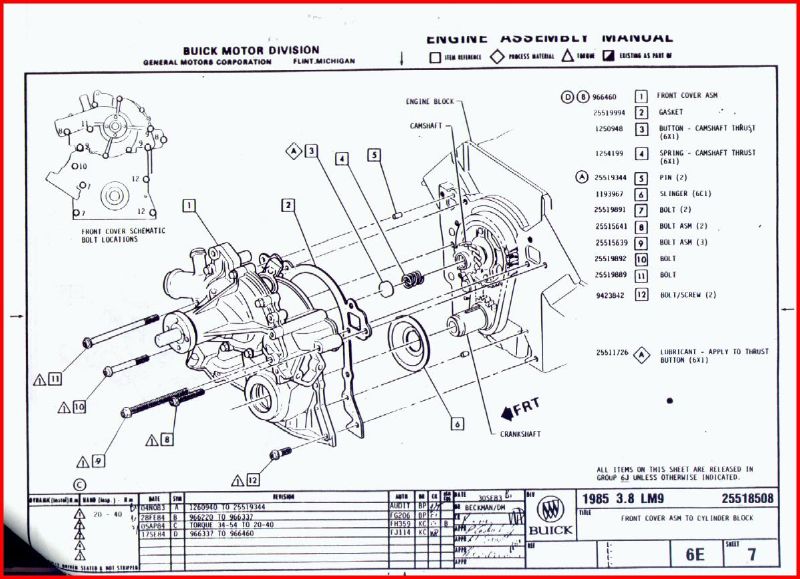
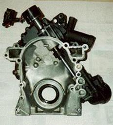
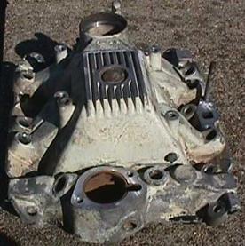
Production 3.8 Liter Turbo Timing Cover |
|
Casting number |
REAR |
DETAIL |
|
|
|
|
Features of Note:
|
Features of Note:
|
|
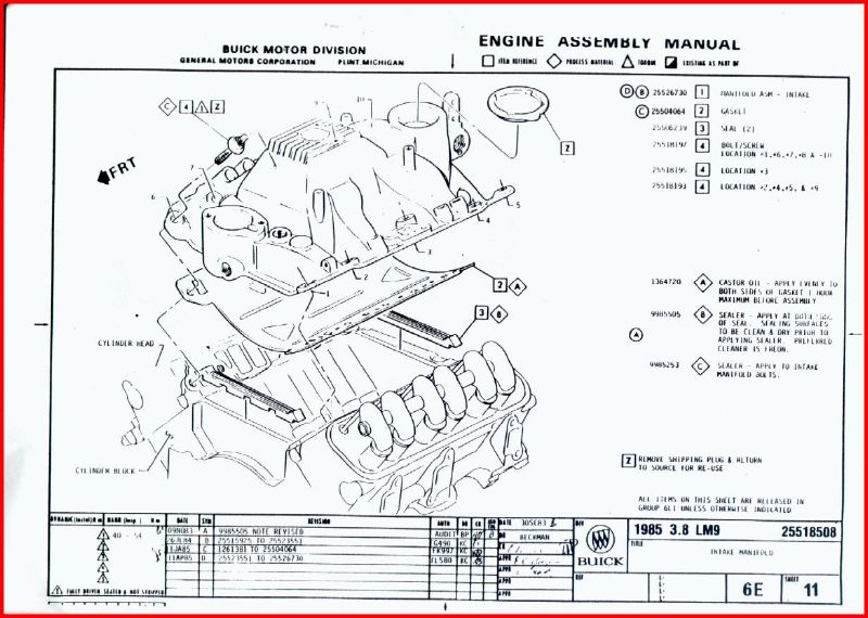
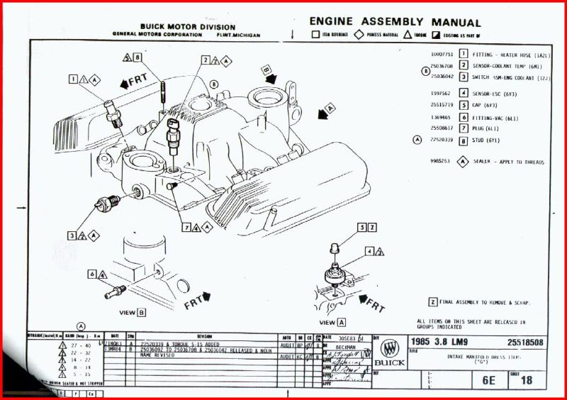
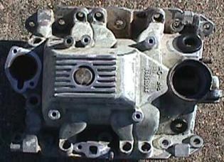
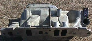
Production 1984-1985 Turbo 3.8 Liter Intake |
|
Casting number 25515926 |
TOP |
SIDE |
|
|
|
|
Features of Note:
|
Features of Note:
|
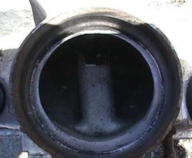
BOTTOM |
TURBO INLET |
|
|
|
|
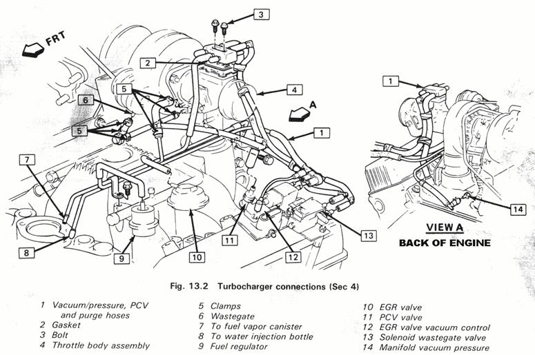
Features of Note: The bottom of the intake shows some of the flow path. Air enters the intake flows to the front of the intake and turns back and is distributed to the intake runners. |
Features of Note: The intake hole for the turbo is split directing the flow to the right and left separately with the EGR port in the middle. You can see where the EGR port comes through the intake from the head, it is directed to the turbo inlet through the valve and pipe(not pictured) to a large threaded hole on the side of the turbo inlet port on the intake |
BACK |
FRONT |
|
|
|
|
Features of Note:
|
Features of Note:
|
|
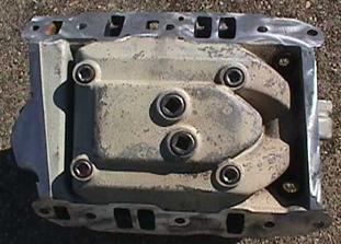
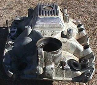
Production 1984-1985 Turbo 3.8 Liter Intake |
|
Casting number 25515926 |
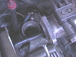
TOP |
TURBO MOUNTING |
|
|
|
|
Features of Note:
|
Features of Note:
|
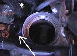
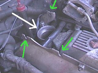
MOUNTING |
TURBO INLET |
|
|
|
|
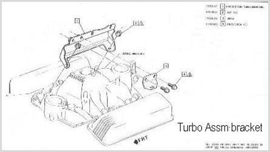
Features of Note: Turbo inlet adapter plugs into the large hole (white arrow) Green arrows indicate mounting points for the turbocharger itself |
Features of Note:
|
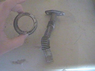
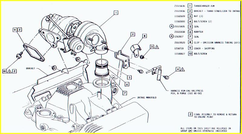
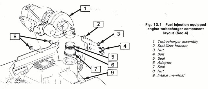
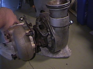
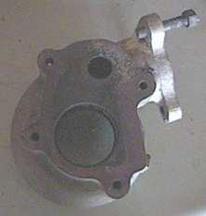
Stock 1984-1985 Turbocharger |
||
|
Stock |
||
BOTTOM |
FRONT/COMPRESSOR |
|
|
|
|
|
|
Features of Note:
|
Features of Note:
|
|
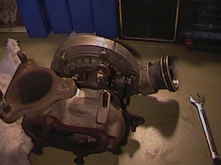
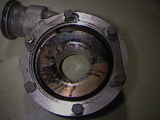
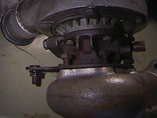
INSIDE COMPRESSOR |
BOTTOM/TURBINE |
|
|
|
|
|
|
Features of Note: This is an interesting view of the inside of the compressor housing Notice the oil residue...evidently the compressor seal on this particular turbo was leaking The compressor inlet hole is pretty small Again, you can see the O ringed adapter piece that fits into the intake manifold |
Features of Note: Notice the turbine scroll is "fatter" and smaller than the '86/87 This shows the separate inlet adapter with the O ring pretty clearly This is the bottom of the turbo and you can see the oil return, which is pretty standard |
|
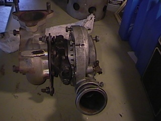
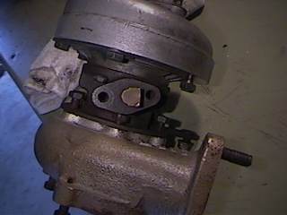
CENTER SECTION |
TOP |
|
|
|
|
|
|
Features of Note:
|
Features of Note:
|
|
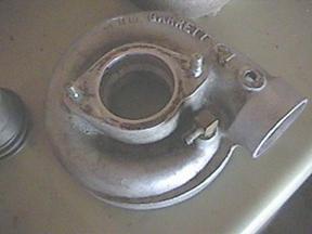
COMPRESSOR |
EXHAUST/TURBINE |
|
|
|
|
|
|
Features of Note:
|
Features of Note:
|
|
|
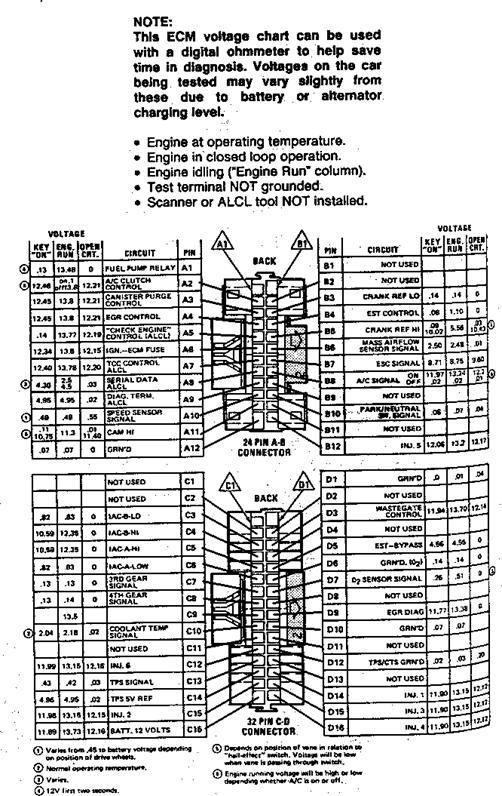
Fuel Injection ECM Pinouts |
|||||||||||||||||||||||||||||||||||||||||||||||||||||||||||||||||||||||||||||||||||||||||||||||||||||||||||||||||||||||||||||||||||||||||||||||||||||||||||||||||||||||||||||||||||||||||||||||||||||||||||||||||||||||||||||||||||||||||||||||||||||||||||||||||||||||||||||||||||||||||||||
| Scott Simpson | |||||||||||||||||||||||||||||||||||||||||||||||||||||||||||||||||||||||||||||||||||||||||||||||||||||||||||||||||||||||||||||||||||||||||||||||||||||||||||||||||||||||||||||||||||||||||||||||||||||||||||||||||||||||||||||||||||||||||||||||||||||||||||||||||||||||||||||||||||||||||||||
|
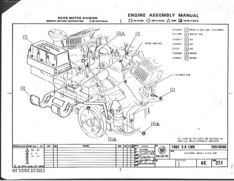
1986 & 1987 3.8 Liter Turbo Engine |
|||||||||||||||||||||||||||||||||||||||||||||||||||||||||||||||||||||||||||||||||||||||||||||||||||||||||||||||||||||||||||||||||||||||||||||||||||||||||||||||||||||||||||||||||||||||||||||||||||||||||||||||||||||||||||||||||||||||||||||||||||||||||||||||||||||||||||||||||||||||||||||
|
This ECM Chart is for use with a digital voltmeter to further aid in diagnosis. The voltages you get may vary due to low battery or other reasons, but should be close. The ECM has 2 connectors: 1 24-pin (A&B) and a 32-pin (C&D) The following conditions must be met before testing:
Notes:
|
|
Cam Sensor Frequently Asked Questions |
||||||||||||||||||||||||||||||||||
| Tom Chou | ||||||||||||||||||||||||||||||||||
|
Cam Sensor Basics |
||||||||||||||||||||||||||||||||||
|
If we're discussing a DIS on a TR, well after 10 years I'm surprised there's still confusion.
|
|
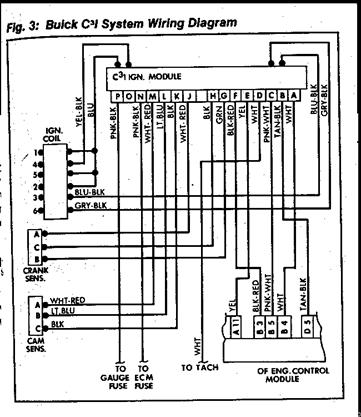
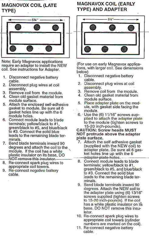
C3I Ignition Module Swap for '84/85 Turbo Regals |
||||||||||||||||||||||||||||||||||||||||||||||||||||||||||||
|
David A. Arieno |
||||||||||||||||||||||||||||||||||||||||||||||||||||||||||||
|
C3I Ignition Module Connector Pin Out for using an '86/87 Module on an '84/85 Turbo Regal |
||||||||||||||||||||||||||||||||||||||||||||||||||||||||||||
|
IMPORTANT!!
|
||||||||||||||||||||||||||||||||||||||||||||||||||||||||||||
|
Alternate Method |
||||||||||||||||||||||||||||||||||||||||||||||||||||||||||||
|
-VERY IMPORTANT! -MARK ALL WIRES TO THE IGNITION MODULE
CONNECTOR WITH TAPE.
|
||||||||||||||||||||||||||||||||||||||||||||||||||||||||||||
|
1984-85 Turbo Regal C3I Ignition Module Connector Pinouts |
||||||||||||||||||||||||||||||||||||||||||||||||||||||||||||
|
||||||||||||||||||||||||||||||||||||||||||||||||||||||||||||
|
1986-87 Turbo Regal C3I Ignition Module Connector Pinouts |
||||||||||||||||||||||||||||||||||||||||||||||||||||||||||||
|
||||||||||||||||||||||||||||||||||||||||||||||||||||||||||||
|
TURBO REGAL C3I IGNITION MODULE CONNECTOR PIN OUTS (CONTINUED) |
||||||||||||||||||||||||||||||||||||||||||||||||||||||||||||
|
HYBRID '84-'85 HARNESS CONNECTOR
|
|
IAC Reset Procedure with a Scan Tool |
| Ken Mosher |
|
Procedure |
|
The ECM controls idle rpm with the IAC (idle air control) valve. The idle rpm is programmed into the PROM. To increase idle rpm the ECM moves the IAC valve out allowing more air to pass by the throttle plate. To decrease rpm it moves the IAC valve in to reduce air past the throttle plate. A scan tool will read the ECM commands to the IAC valve in counts. Higher the counts the more the air is being allowed to pass the throttle plate (higher idle). Lower the counts the less the air is being allowed to pass the throttle plate (lower idle).
|
|
Adjusting the TPS |
|
Objective |
|
To adjust the Throttle Position Sensor to recommended settings of between 0.40-0.46 volts at idle and between 4.5 and 4.8 volts at Wide Open Throttle (WOT). This procedure should be performed after the minimum idle air settings are already made (via the IAC reset procedure). |
|
Equipment Needed |
|
The following tools are needed:
|
|
Procedure |
Note: Occasionally a TPS will need the moon shaped grooves honed out a bit with a rat tail file to get enough adjustment, but normally the trick of moving the sensor as far forward as possible gives enough adjustment. Also, be very careful around the little roll pin that rests on the throttle lever, since it can bend or break. |
|
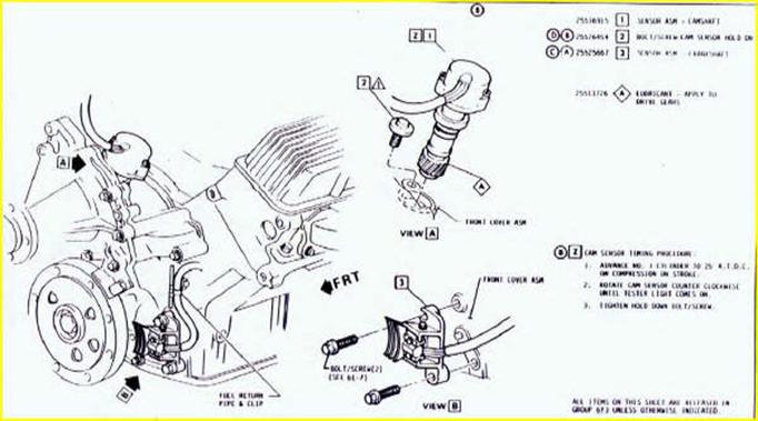
Cam Sensor Adjustment Procedure |
||||||||||||||
|
Cam Sensor Adjustment Procedure |
||||||||||||||
The sensor is a hall effect device with a rotating metal ring that is driven from the front of the cam gear via a shaft (like a distributor). This ring passes thru a grooved sensor molded into the sensor cap. The metal ring has a notch or window cut out of it. When the window goes by the sensor, the voltage drops, which tells the ECM where #1 TDC is. Jim Frankovich has done some measuring and calculating and has the following input:
Several people have found that when running a bigger cam with advanced valve timing, it sometimes will help cure a popping or sputtering symptom by advancing the cam sensor a few degrees. The above values give you an idea of what to shoot for. |
|
Cam Sensor Information and C3I Module Pinouts |
||||||||||||||||||||||||||||||||||||||||||||||||||||||||||||||||||||||||||||||||||||||||||||||||||||||||||||||||||||||||
|
Cam Sensor Adjustment Procedure |
||||||||||||||||||||||||||||||||||||||||||||||||||||||||||||||||||||||||||||||||||||||||||||||||||||||||||||||||||||||||
The sensor is a hall effect device with a rotating metal ring that is driven from the front of the cam gear via a shaft (like a distributor). This ring passes thru a grooved sensor molded into the sensor cap. The metal ring has a notch or window cut out of it. When the window goes by the sensor, the voltage drops, which tells the ECM where #1 TDC is. |
||||||||||||||||||||||||||||||||||||||||||||||||||||||||||||||||||||||||||||||||||||||||||||||||||||||||||||||||||||||||
|
Cam Sensor Adjustment Procedure with an Oscilloscope |
||||||||||||||||||||||||||||||||||||||||||||||||||||||||||||||||||||||||||||||||||||||||||||||||||||||||||||||||||||||||
|
||||||||||||||||||||||||||||||||||||||||||||||||||||||||||||||||||||||||||||||||||||||||||||||||||||||||||||||||||||||||
|
C3I Module Pinouts |
||||||||||||||||||||||||||||||||||||||||||||||||||||||||||||||||||||||||||||||||||||||||||||||||||||||||||||||||||||||||
|
1984-1985
1986-1987
|
|
Alternative Cam Sensor Adjustment Procedure |
||||||||||||||||||||||||||
| Scott Walsh | ||||||||||||||||||||||||||
|
Cam Sensor Adjustment Procedure |
||||||||||||||||||||||||||
|
NOTES: This procedure is easier if all sensors are disconnected. There are several sensors in the area and removing the wiring harnesses make your job easier. The intercooler does not have to be removed but removal of it and your serpentine belt will make rotating the engine easier. You must also remove the up pipe and intake hose between the MASS air sensor and the turbo.
|
|
86/87 ECM Car List |
||||||||||||
| Marvin Ballard - marvinballard@bigfoot.com | ||||||||||||
|
ECM List |
||||||||||||
|
The following is a list of cars that have the same ecm as the '86-87 GN's and T-Types. They are suppose to be direct replacements less the prom: I received this list while at the junk yard. It was generated from there computer using Hollander Number: 590-1554 Electronic Engine Control Module Hollander Listing.
|


|
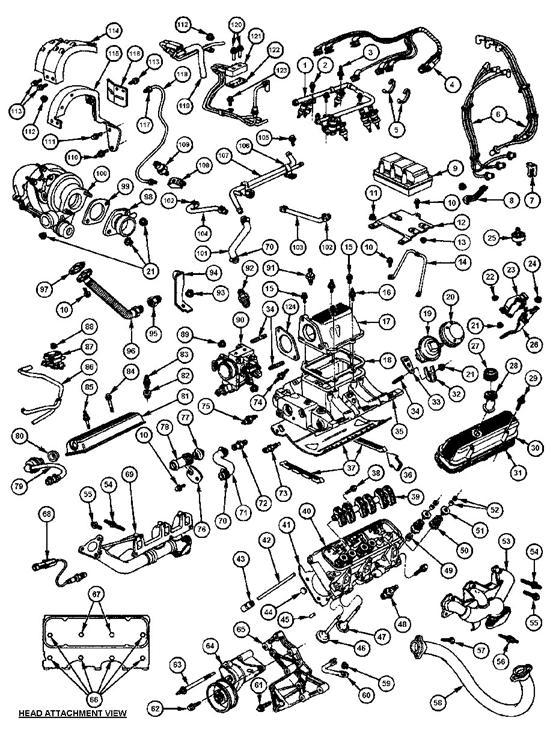
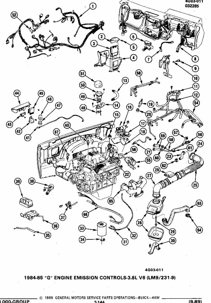
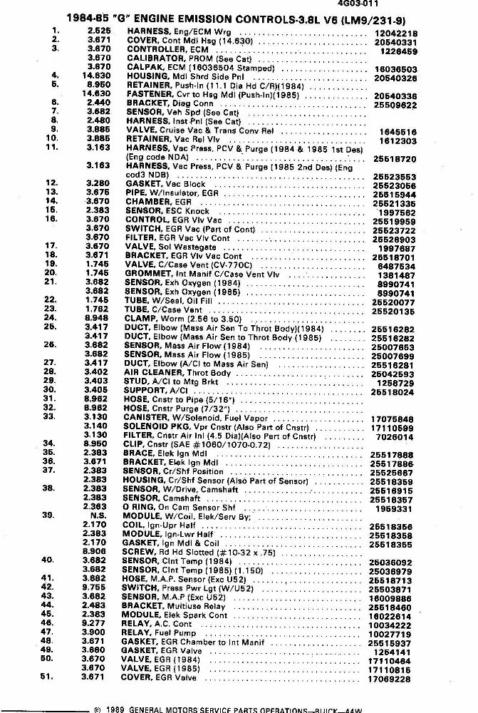
1986-1987 Exploded Parts Diagram |