Vega/LT1 Conversion Tips: A collection of information
from VARIOUS websites
700R4
- The 700R4 fits in a 75 and later H-body. You don’t have to cut a hole in the floor, there is plenty of room, BUT you do have to cut about 4 or so inches out of the front part of the tranny crossmember mount NOT THE CROSSMEMBER! This still leaves the rear mounting hole in the bracket to work with. The stock crossmember works fine and so does the stock H-body tranny mount. The front hole in the crossmember lines up with the back hole (the last of 3). To install H-body 3rd link torque arm, make sure the tranny has the Camaro/Firebird tail housing, rotate the torque arm bracket 90 degrees and use the two holes closest to the front. With these mods you have to shorten the drive shaft and the torque arm. Cut the drive shaft around 2 inches. Cut the torque arm about 6 inches from the front. You may also have to move the crossmember back about two inches to line up with the transmission mount.
- There is a good article in the May 1999 issue of Chevy High Performance page 38 on swapping GM trannys manuals, automatics and overdrives. You have to do a little back and forth reading through the article to compare dimensions but it can give help on crossmember locations, and driveshaft length changes.
- Shifter: You can use the
older style with T-handle and pull up lever lock out- most needed parts from a
1986 Camaro.
-- Grab:
shifter, shifter cable, both shifter brackets on the tranny
1. Measure the centerline between the Camaro shifter pivot points and where
the cable hooks up.
2.
Weld a pin to mount the cable on the Monza shifter (it was a rod type
shifter) at the same distance found in step one
3. Cut the portion that holds the cable on the shifter base and welded it to the Monza shifter (again measure)
4. You can also make a gate so when you upshift from 1st to 2nd you only have to push the shifter; 2nd to 3rd you will have to pull the lever and push the shifter, and 3rd to 4th I didn’t do any gate work there-- most of the time you’re not in a hurry to shift in this range.
One tip that can also help you
-- try doing all the assembly (trans+shifter) while it’s out
of the car... it makes it easier to sort out bugs
- Torque Converter: The '95 or later Chevrolet S-10 4.3L 4L60E torque converter is the highest stall factory lockup converter that will bolt to the 700R4/4L60E. This will increase stall to about 2200-2500 rpm, and significantly improve off the line performance. This converter costs about $200 new, but a remanufactured version can be had for about $150. The part number is 24202310. Since this is still a factory converter and it does include lockup, the effect is not too wild, and cruise fuel economy is not affected much. Although a higher stall converter does increase the heat load, the transmission cooler in the Impala should be up to the task, and if not the 9C1 cooler could be added.
Dual Exhaust
- Run both pipes on the passenger side, right next to each other and then up and over the rear end and put both mufflers side by side next to the gas tank, where the stock muffler was. I am using 2 1/4" pipe, with an H pipe, and Edelbrock stainless mufflers. It's a tight fit but looks and works real well. Doing it this way also gave me some ground clearance and you don't see the mufflers hanging way down under the rear seats. This works very well on a Monza- the Vega muffler mounts behind the rear axle, so it will be a bit tougher to adapt duals if you keep the muffler in the stock position.
SPEEDOMETER
Speedometers are pretty easy to adapt. The actual 'rate' of speedometers is all the same. What changes is the pickup gear in the transmission. This is how I think of it. Within the Vega lineup: If a Vega is moving at 60 MPH, the tires are covering the ground distance at that 60MPH. Staying with a standard tire size, all tires rotate at the same revolutions per minute. Different rear end gears will require the drive shaft to turn at different rates. (Faster for 4:11 gears, slower for 2:93 gears). The speedometer pickup is in the tailshaft of most transmissions. It turns in proportion to the drive shaft. No matter how fast or slow the engine is turning, or what gear the transmission is in, the speedometer picks up number of turns from the drive shaft. Since rear end gears change the number of drive shaft revolutions per measure of distance, then the pickup gear has to change based on the rear axle gear. GM color-codes these pickup gears. Find the pickup gear that goes with the rear axle you will use. Or, consult a parts man about which gear is correct.
All speedos are standardized for 1000 cable turns per mile. First get the tire diameter. This can be calculated using the following formula:
Tire Diameter
=![]()
![]()
So for a car using 205-60R14’s
2 x 205/25.4 x .60 + 14 = 23.7 inches
Next, calculate you tire revs per mile. Dividing the diameter in inches into 20,800 easily approximates this. Then multiply by the axle gear. Now you have driveshaft revs per mile.
20,800/23.7 = 878 x 3.42 = 3002 driveshaft revs per mile.
You then need a speedo gear to get this down to 1000 revs per mile. Example,
205/60R14 turns 878 revs per mile. With a 3.42 gear, the driveshaft turns 3002
revs per mile. This car needs a 0.333 speedo gear ratio.
Drive gears are available in 7,8,9 or 10 teeth; driven gears from 17 thru 25. So for my car, 7 and 21 will be very close.
Wiring an In-Dash Tachometer to the LT1
- Once it fits in well, make sure the wires are routed so that they'll dangle into the area below the instrument panel and replace the bezel.
- The wires for the tach should be dangling down there, or at least accessible from under and behind the instrument panel. Installing a four-way connector here would be a good idea in case you ever need to remove the tach.
- Tap in a "dimming" or "lights on" signal. The any of the dash lights have both a dimming lead and a ground wire going to its light. The wires are also free enough to work with. The grey wire is the dimming wire, and the black wire is the ground.
- To get power to the tach, you might want to tap into one of the orange wires at the bottom of the fuse box. Check a shop manual for details: you want one that is only hot during run.
- To get the actual tachometer lead hooked up, you need to route it through the firewall using a factory, unused grommet. Use a sharp point to poke a hole in the plug in the firewall, and then squeeze the 18 gauge wire through it. You might have to fish it through using a coathanger or something.
- The tachometer can take its signal from the black and white wire (negative) terminal at the coil pack on the front of the LH cylinder head. Alternatively, another member has plugged the lead into fourth, unu999999sed female terminal on the coil. The both go to the same spot.
- Another good place to get a tach signal would be from the PCM connector pin A13. All B/F-car PCMs output the tach signal on this pin. You will need a terminal p/n 12084913 (for 20 ga. wire) to install in the PCM A connector (the factory uses a white wire for this application).
- The wires should be inserted inside of factory ribbed conduit. You can cut a short length and route to one of the factory conduits from the firewall grommet, or route a new conduit all the way to the coil pack.
Coil Spring Applications and Specs
FRONT Coil Spring Applications ============================== W/O A/C With A/C 1980 Monza 4 cyl hatchback coupe and sport coupe cs-6490 cs-5622 4 cyl notchback coupe cs-6490 cs-6490 6 cyl Hatchback & Notchchback coupe cs-5622 cs-5624 6 cyl Hatchback Sport coupe cs-5624 cs-5624 1979 Monza 4 cyl 2+2 hatchback Sport coupe cs-6490 cs-5622 4 cyl hatchback & notchback coupe cs-6490 4 cyl station wagon cs-6488 cs-6490 6 cyl hatchback & hatch sport coupe cs-5622 cs-5624 6 cyl nothcback coupe cs-5622 cs-5624 8 cyl hatchback & notchback coupe cs-5624 cs-5626 8 cyl hatchback sport coupe cs-5626 cs-5576 1978 Monza 4 cyl hatchback "S" coupe cs-6490 cs-6490 4 cyl hatchback coupe & sport coupe cs-6490 cs-5622 4 cyl nothback coupe cs-6490 cs-6490 4 cyl station wagon cs-6490 cs-6490 6 cyl 3.2 hatchback & notchback coupe cs-5622 cs-5624 6 cyl 3.2 notchback coupe cs-5622 cs-5622 6 cyl 3.8 hatchback "S" coupe cs-6490 cs-5622 6 cyl 3.8 station wagon cs-6490 cs-5622 8 cyl (ALL) cs-5626 cs-5576 1977 Vega ALL cs-6488 cs-6490 1977 & 1976 Monza 4 cyl 2+2 hatchback coupe cs-6490 cs-5622 4 cyl notchback Towne coupe cs-6490 cs-6490 8 cyl ALL cs-5626 cs-5576 1976 & 1975 Vega ALL cs-6488 cs-6490 1975 Monza ALL cs-6490 1974 Vega ALL (exc. station wagon) cs-6434 Station wagon 1973 Vega All cs-6434 1972 Vega All cs-6434 1971 Vega cs-6434
All REAR Coil Spring Applications ============================== All years and models CS-6377 (constant rate) CS-617 (Variable rate) Coil Spring Specifications
P/N wire diam. installed installed installed spring free
in inch height load(lbs) rate (Lbs/inch) height
Front Coils
CS-5576 0.625 9 1814 384.5 13.690
CS-5622 0.590 9 1555 308.0 14.152
CS-5624 0.590 9 1640 309.0 14.430
CS-5626 0.590 9 1740 309.0 14.728
CS-6434 0.593 9 1306 373.2 12.520
CS-6488 0.590 9 1359 330.1 13.130
CS-6490 0.590 9 1465 317.9 13.630
Rear Coils
CS-6377 0.504 10.25 484 141.1 13.690
CC-617 0.565 10.25 475 156.0 13.310
ADJUSTING V-8 SPRING HEIGHT
To make up for the shallower spring pockets in the pre-1975 lower control arms you'll need to cut 2 rounds from the springs. Caution: 1) Do not use a torch to cut the springs, as the heat will ruin them. 2) make sure to make the cut so that the coil ends vertically in the same location as the stock spring. It needs to fit back in the spring pockets on both ends of the spring. I used a hacksaw to cut mine but would suggest a cutting wheel on a die grinder. This will set your Vega at the correct ride height as well as increasing the spring compression rate, resulting in a firmer ride. I really liked the results.
Steering:
K6196 Idler arm
ES425RL Outer tie rod end (need 2)
ES681N Inner tie rod end (need 2)
ES2032S Adjusting sleeves (need 2)
DS816 Center link, 71-76 manual steering, 77-78 4 cyl manual steering
DS889 Center link, 71-76 power steering, 77-78 4 cyl power steering,
Front Suspension:
K6118 Upper ball joint (need 2)
K6157 Lower ball joint (1975-1980) (need 2)
K6119 Lower ball joint (1971-1974) (need 2)
K6112 Upper control arm bushing kit (OEM-style) (need 2)
K6155 Upper control arm bushing kit (offset) (need 2)
K6113 Lower control arm bushing kit (need 2)
K6158 Lower control arm shaft kit (need 2)
K5241 Sway bar bushing (15/16 and smaller)
K5253 Sway bar bushing (1" and bigger)
Rear Suspension:
Vega (pre-1976):
K6114 Upper control arm (need 2)
K6115 Lower control arm (need 2)
Monza and 1976-up Vega:
K6166 Torque arm
K6115 Lower control arm (need 2)
K6180 Track bar (aka Panhard rod)
K5241 Sway bar bushing (15/16 and smaller)
K5253 Sway bar bushing (1" and bigger)
Note: If you can't find Monza pieces, use bushings for a 3rd-gen ('82-'92) Camaro Panhard rod.
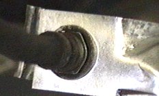
Pot Joint Boot: the boot for the pot joint is the same as one from a 1986 Jeep CJ, which is much easier to find than one for an H-body.
Addco sells swaybars for most cars. For Monza:
· 885 front: 1 inch
· 710 front: 1 1/8 inch
· 984 rear: 7/8 inch
· 672 rear: 1 inch
PST sells polygraphite bushings.
KYB sells GR-2 velocity sensitive shocks.
Energy Suspension makes bushing kits:
· 3-3140 rear for pre-1976 Vega
· 3-3141 rear for 1976-up Vega and all Monza
· 3126 front end
· 9-8117 swaybar endlinks (made of urethane)
Factory alignment recommendation for a 1977 Warranty | For inspection | Specs 4 resetting
Caster -1.8 to +. 2 | -2.8 to +1.2 | -.8 +/-.5
Camber -.6 to +1.0 | -1.3 to +1.7 | +. 2 +/-.5
Toe in (degrees) -.19 to +. 06 | -.42 to +. 31 | -.06 +/-.06
What effect does swapping my upper control arms side-to-side have?
Swapping the arms side-to-side greatly increases the caster angle. More caster makes the car go straighter with more effort to steer. The car is more stable, because the steering doesn't react quite as quickly due to the extra caster. You can swap the upper control arms side to side and get about 9.5 degrees of caster. A small amount of grinding needs to be done. I have done this to my '78 Monza that I run at Bonneville. I also cut two coils and use Moog upper offset bushings to restore the camber (the car is stable to well over 200 mph). 10.0 extra caster would probably work on the street but may cause other handling problems. The offset bushings are the route I would go if the car sees street driving.
What is a good road racing or autocross suspension setup?
Not too much here for specifics, but basic ideas:
- If you have an early car, convert to the later torque arm suspension.
- Sticky tires (duh).
- Stiffer springs.
- Race/competition shocks (Koni (no longer available), Carerra, KYB)
- Larger sway bars.
- Polyurethane bushings on panhard rod (or upper control arms) and lower control arms. NOTE: Using poly bushings on both ends of the control arm will cuase binding--use regular rubber on one end.
- Polyurethane bushings up front too!
- Negative camber. Zero toe.
- As much caster as you can get. Swapping the upper A-arms side to side can give you a lot of caster.
Rear Suspension
3 Link (Torque Arm)
and 4 Link Suspensions
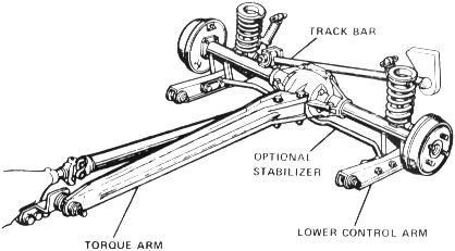
The factory 3-Link Torque Arm Suspension was the best design by far. It eliminated wheel hop for even the V8 cars and was the predecessor to the Corvette and Camaro Torque Arm suspensions.
Reinforcing Rear Lower Control Arms
You can take the stock Vega lower control arms and drill
them to accept the sway bar. First, you will need to take a section of
2.5" plastic pipe and cut it in half. This will leave you with 2 'half
moon' pieces of pipe. You will trim these until they slip into the control arm
around the bushings. This will keep the arms from collapsing when pressing bushings
in & out. Next, take an 8" section of steel tubing and lay it in the
channel of the control arm. I used a piece of old porch railing from a trailer
and cut out two (8) sections for my control arms. It is very, very thin and
light. But, it does the job even when the sway bar is torqued to 50 ft/lbs.
When the sway bar is bolted in place, the arm becomes very, very solid.
However, the total weight of the arm with bushings is less than the fully boxed
lower control arm. You could tack weld it in place, but because I have a rear
sway bar anyway, I just let the action of bolting the sway bar in place keep
the insert tight. This is quick, easy, and strong and requires no welding. You
can do both arms in about 15 minutes.
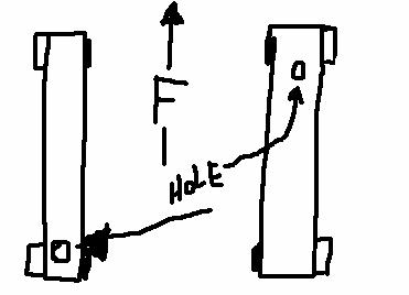
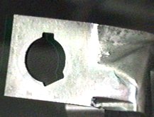
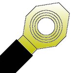
When installing the arms in the car, you will notice a 3/8" hole on the
top of each arm, offset towards one end. In stock configuration, both holes
face the rear and the flanges of the bushings (the bigger end) all face to the
left. It is important to offset the flanges so they will keep the rear end in
alignment during cornering. The drawing below explains the directions the
flanges face and how the holes should look when the arms are properly
installed.
![]()
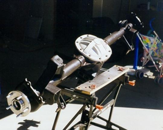
REAR END FROM S-10
The 3-link rear suspension setup in all Monzas and post-'75 Vegas is very good. It is similar to the H-Body configuration and the Third and Fourth Generation F-Body designs. The Camaro/Firebird setup from 1982 on was designed around the H-Body configuration. With that said, you can't find a much better setup for all-around performance than the stock configuration offered by the ’75 and later H-Bodies.
Be aware not all ’75 and later H-body rear-ends are the 7.5” diameter type. From 1976-1977, the Vega used either a 6.5” or a 7.5” rear end. From 1978 on, all H-bodies were 7.5” diameter. See the http://h-body.org/ FAQ website for details on where to find rear axle codes and matching ring gear diameters.
If you are putting out more horsepower than stock, it is probably a good idea to update the rear end in your H-Body. The stock 6.5" rear end in a Vega is a bomb waiting to go off. While the 7.5" found in Monzas and others is better, it probably won't hold up very well over 300 hp.
You can use the rear end out of an S-10 Truck. Try to find a 4-cyl truck since they usually have a 4.11 gear and sometimes a posi unit. The S-10 rear will hold up pretty well until you start making mega-power. You will have to weld all the brackets from the Vega rear to the S-10 rear. Because the S-10 rear is actually 1" narrower than the Vega rear, you can work with backspacing to get a 9-10" tire in the fender without tubs! You also get the five-lug pattern with the S-10 rear.
It is possible to use just the axles, ring, and pinion from an S-10 rear end with some changes to different bearings. Instead of using the whole rear end from an S-10, you can also just use the axles from an early '80's 2wd S-10 You can only use 2-wheel drive Chevy S-10 and Blazer axles for a 5-lug upgrade. The axles are the same spline (26 spline) and are only 1/16" shorter than the stock Vega axles. This makes a 5-bolt swap easy. Grab the larger drums and backing plates from the S-10 as well. Besides being larger, they are often finned (better cooling) and some of them are aluminum (lighter). This swap will only work with '76 and up 7.5" rear ends.
In some cases the shorter axles result in the rear brake drums (also 5-lug) rubbing against the rear backing plates (dust covers) around the edge where the drum meets the back cover. The backing plates may have to have about 1/16" shaved of the lip facing the drum to prevent rubbing. Mine do not rub, but if you find that yours do just remove 1/16th inch from the edge of the backplates. To do this, I would suggest scribing the backplates 1/16th inch in and using a handheld grinder, remove the excess metal. Then smooth the edge with either a file or sandpaper. NOTE: 1975 and earlier vehicles have 9" diameter by 1" wide brakes and therefore a smaller backing plate. Later model (1976 to 1980) backing plates will be required for this modification.
The 7.5" Chevy S-10 gears will fit the H-Body case, but the main problem is that, in the differential case, the hole for the pinion bearing is smaller in the H-body differential than in other GM 10-bolt differentials. You can either get a machine shop to enlarge this hole or use a special pinion bearing and race.
You’ll need; S-10 gears, S-10 posi unit (if it’s posi), and S-10 axles (2 wheel drive only!) S-10 rear end yoke, S-10 drums (if you use the S-10 axles). If you reuse the Vega axles, check if the carrier of the S-10 is a 26-spline unit. The S-10 pinion gear requires Timken bearing #16143, Timken bearing race #16283, and National seal #8610, S-10 pinion yoke, and "Combination" U-joint (Dana #5-3022X). As with most all gear sets a specific gear carrier is required for a specific range of gear sizes, so the carrier must be the correct series for the gear set that you want. In other words, you need to know what series the carrier is or what gears were installed on it from the factory. A 2-series carrier fits 3.08 and numerically lower gears (3.08, 2.93, 2.73, 2.56, and 2.29), while a 3-series carrier fits 3.23 and numerically higher gears (3.23, 3.42, 3.73, and 4.10). The exception to this is if you purchase custom gears specifically made to fit your specific carrier (i.e. you can buy 3.23, 3.42, 3.73, 4.10, and 4.56 gears to fit the 2-series carrier). If you are at all performance minded, you will probably want to have a positraction unit in your H-Body. Stock posi rear ends for these cars are actually quite abundant, but can sometimes be pricey. You can upgrade to a new or different posi carrier by getting a 26-spline carrier of the right series for your gears Auburn also makes an aftermarket posi unit for the 7.5" rear end as well. Also, the Camaro and S-10 7.5" posi unit will fit the 7.5" H-Body rear housing. I have had a posi carrier from a Camaro 7.5 rear installed in my H-Body rear since 1988 and it works fine.
So, the list is:
- Enlarge pinion hole in differential and use S-10 bearing,
race, and seal
-OR-
Use these non-factory parts:
Timkin bearing #16143,
Timkin bearing race #16283, and
National seal #8610. - 7.5" gear set with pinion
- New carrier if the new gears won't fit your current carrier (see 3.10)
- S-10 rear end yoke
- "Combination" U-joint (Dana #5-3022X) to mate the S-10 yoke with your stock driveshaft
NOTE: Installing new gears requires setting the proper pinion depth and carrier position. Doing this wrong will destroy your gears. Even the most die-hard shade tree mechanics leave this to a professional. If you want to try it anyway, this is the basic procedure and tips from Robert (twelve_second_vega): "When you pull the carrier, mark the shims on the side of each bearing. They are cast iron and must be handled with care. Put a new crush sleeve on the pinion and install it in your 7.5" housing. Set the preload (about 10 inch pounds with used bearings) and set the carrier in place. Gently tap the shims you took out into place with a PLASTIC hammer and torque the caps. Only once did a gearset need to be reset. 99% of the time, you can just throw them in and go. If the backlash is off (.005" - .008" with used gears) you will need different shims. Subtract the amount you need (in backlash reduction) from the right shim to move the ring gear deeper into the pinion. BE SURE to add this SAME AMOUNT to the opposite shim. You MUST maintain the preload on the side bearings. When properly set-up, you will have to pry the carrier out of the housing and putting shims back in should not be easy either."
Ring/Pinion Swap Specs
(Turn the S-10/F-body pinion down .060")
H-body pinion O.D. (rear bearing): 1.3755”
(front bearing): 1.1875”
S-10 pinion O.D. (rear bearing): 1.975”
(front bearing): 1.1875”
Cover gasket: Victor #P2782 (NAPA) or Fel-Pro #55072
Bearings (axle): JM14070 (?); Torrington DB67309; NAPA R1563-TAV
Seals (axle): NAPA #13992
Bearings: (pinion, front, H-body & S-10): NDH #M86649A; John Deere AR94761
(pinion, rear, H-body): Timken #HM88649A
(pinion, rear, S-10, stock):
Timken #HM89249
Races: (pinion, front, Buick & S-10): HDH #M86610CJ
(pinion, rear, H-body): Timken #HM88610A
(pinion, rear, S-10, stock):
Timken #HM89210
Seal (pinion): National #8610
Differential carrier bearings: Timken #LM501349
Differential races: Timken #LM501314
How to build a better 10-bolt
I have always had a problem with the rear axle
that came with my Trans Am: Known as RPO Code GT4, my original axle assembly
came equipped with ten-inch rear rotors, coupled to 26-spline axles that were
splined to an Eaton Guv-lock differential with a 7.5-inch 3.73:1 gearset. Now I
imagine that this was an acceptable performance piece when the car was new, but
with only 39,000 miles on the car, the clutches had already worn out. This
becomes a problem with the Eaton unit, as the system will free-wheel like an
open differential then lock solid with a bang. I lived with this malfunctioning
differential for 90,000 miles! Since I was going to race this year, the LAST
thing I wanted to happen was an unexpected lockup of the differential. It
upsets the whole suspension and will quickly send you into a spin. It usually
happens in conjunction with a hard upshift. Another problem with the GT4 is the
original RPO J65 rear disk brakes: They have a faulty spring inside the piston
that causes them to retract from the brake rotor. This results in excessive pedal
travel, and no emergency brakes. Mine were corrected with a set of revised
pistons from GM, but when I broke off a bleeder screw in the left caliper, I
knew it was time to update.
My goal is to design a rear axle assembly that will hold up to about 400 horsepower. I looked at buying a 12-bolt, but parts are too expensive and hard to find. I looked at getting a Dana 44, but they were non-existent. A Ford 9-inch has alignment problems, and is easily $1500 for an entry-level assembly. What I settled on is the only solution that costs under a thousand dollars: A 10-bolt that uses the Gleason/Torsen heavy-duty Torsen differential, and aftermarket axles.
|
10-bolt Performance The Torsen heavy-duty differential is a unit that is currently being sold in the 1999 Pontiac SLP Firehawk. The LS-1 based Firehawk outputs about 345 rear-wheel horsepower, and offers a warranty to boot. Therefore, a goal for a 400-horsepower capable 10-bolt seems attainable with this differential. Research indicated that the Torsen is a direct bolt in to any 3-series 10-bolt carrier. Thus, the Torsen should be able to fit in my 1984 GT4 axle housing. Unfortunately, the GT4, being a pre-1989 axle, uses 26 spline axles whereas the Torsen employs 28-spline axles. Therefore, a new set of axles is in order. For these axles, I called Greg Moser of Moser Engineering. Moser Engineering can cut a set of 28-spline axles for the third-generation F-car or an H-body which are much more capable of handling the high-torque demands of a performance application. Thus, the Moser axles were chosen in favor of stock 28-spline axles from a junkyard. There have been reports of broken OEM axles squirting out onto the racetrack and I want to avoid this possibility. REAR DISK BRAKES '98 and newer Camaro and Blazer share the new brakes with aluminum calipers and separate drum style parking brake. The rear caliper pistons are 1.900-inch diameter (38 mm). When you connect the brake lines to the rear calipers, make sure you use some short flex hose because the caliper moves relative to the axle. The best method is to use hard lines from the brake hose T to each end of the axle and weld a small bracket to hold the line. Then use about 6 inches of flex line to the caliper. This flex line will have a banjo fitting on the end and attach right to the caliper with a hollow bolt. |
|
 Rea
Rea
|
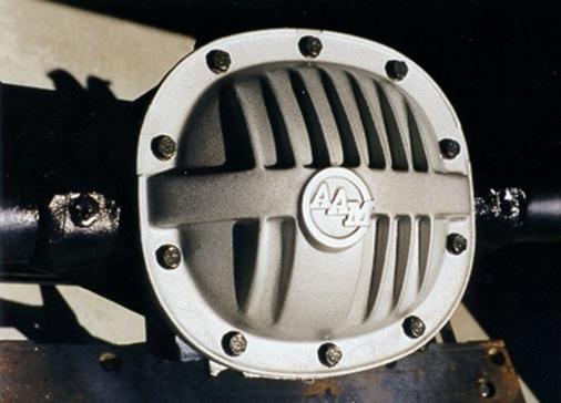
AAM Oil-cooling Differential Cover This cover has a patented oil cooler cast inside it. I saw a lexan version of this cover in action at the 1997 SAE International congress--- Very snazzy. It catches gear oil as it is flung off the ring gear, and channels it through passages in the differential cover to the holes on either side of the differential case: These holes, normally used for case spreading, open up into the axle tubes on the other side of the differential bearings. The oil is dumped into the axle tubes, where it flows both to the load bearing at the wheels, and back into the differential case. Thus, your axle tubes become a method with which excess heat is drawn out of the oil. The AAM cover is also nearly half an inch thick at the mounting flanges, which should greatly increase the rigidity of the axle assembly. This should further increase reliability of the gearing. |
|
The Torsen heavy-duty differential was purchased through SLP-Performance on their Internet specials page. SLP offers two different differentials: An OEM take-off version, and the heavy-duty version that they installed in the 1999 Firehawk. The OEM is a real bargain, being virtually brand new, and already sporting bearings. Bearings cost $25 or more per pair anyway, so this is a good deal. The heavy-duty version is brand new, without bearings, but comes with a cast aluminum differential cover from American Axle and Machining (AAM). The Torsen differentials are designed for use in a 3-series carrier.
I had a conversation with Richmond engineers a few months ago on the reliability of their 7.5" ring & pinion. I wanted to know if it could hold up to 400 horsepower and they said that 400 horsepower was "pushing it", but that a stud girdle would help greatly in preserving gear life. Richmond claims that the biggest flaw with the 10-bolt design is the flexibility of the case. When under heavy load, the pinion walks up the ring gear face, and forces the case apart. This totally throws off the gear alignment, which causes premature gear failure. The key, according to Richmond, is to maintain alignment by increasing case rigidity. They claim that a stud girdle, like the one offered by Summit Racing equipment, or the TA Performance piece offered by Fast Toys, will "essentially double" the gear life of a differential used under high load conditions. A stud girdle is a very stiff cast aluminum differential cover, with studs that extend to the load bearing caps. It ties the rear of the case to the bearing cap surface, greatly increasing rigidity.
In any event, Richmond said that the useful power range of a 10-bolt stops at 400 horsepower. Further conversations with Steve Spohn along with Phillip Reddy concur with this assessment. They have both experienced failures when power increased above 350 HP, especially under launch with a modified suspension and drag racing slicks.
Troy (QuikGTA@hotmail.com) runs a 1992 Trans Am GTA, and is using Richmond 3.42 gears, National Drivetrain 28-spline axles, and a Summit rear girdle, along with the heavy-duty Torsen differential. He has these suggestions on further increasing the strength of the 10-bolt:
- Use Redline Synthetic shockproof geal oil.
- Weld the axle tubes all the way around, where they go into the housing to increase strength of the housing. The factory only used 2 spot welds here.
- Use a Zytanium cross pin. It is available in the Year One Next Generation catalog for $28.
- Use a solid bearing spacer instead of a crush sleeve. It costs about $20 from Ratech engineering
Related links:
Moser
Engineering: Custom Axles
http://www.partsgm.com/
http://www.auburngear.com/
http://www.slpeng.com/
http://www.spohn.net/index.html
http://www.richmondgear.com/home.html
http://www.summitracing.com/
REAR DISK BRAKES
'98 and newer Camaro and Blazer that share the new brakes with aluminum calipers and separate drum style parking brake. The rear caliper pistons are 1.900-inch diameter (38 mm). Front Monza calipers are 2.500 inches. Together, this system will have a brake proportion of about 62/38, which is not enough front bias, so you will need to use a combination proportioning valve. When you connect the brake lines to the rear calipers, make sure you use some short flex hose because the caliper moves relative to the axle. The best method is to use hard lines from the brake hose T to each end of the axle and weld a small bracket to hold the line. Then use about 6 inches of flex line to the caliper. This flex line will have a banjo fitting on the end and attach right to the caliper with a hollow bolt.
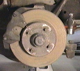
Front Disc Brakes
Get a pair of complete S-10 spindles (around $50). Rebuilt
S-10 calipers and new ’76 Nova brake hoses are available from Auto Zone.
Cross-drilled and slotted rotors fare available from J.C. Whitney or Summit
Racing for $70-80 each. I got new bearings and seals from Autozone. The bushing
adapters from Bob Gumm are Loc-Tighted (red) and installed into the spindles. I
used a plastic hammer to tap them in to ensure they were seated - I didn't have
to trim them. I had to install one lower ball joint because of a boot tear. I
got the tools from J.C. Whitney. The spindles raise the front height by 1 inch.
It's definitely a good swap.
You need to locate parts from a ‘76 Caddy Eldorado with Turbo-Boost 4 wheel
disc brakes. Finding the Caddy in a yard will be the challenge-- I spent
endless hours in junkyards and Auto Zone trying to find a bolt in. You need
the proportioning valve and get the master cylinder for a core. I traded the
core an Autozone for a rebuilt and replaced the Monza stuff. To verify that it
is a disc brake master, compare it to the Monza. It should have the cast
divider in the middle of the master and not biased to one side like the Monza is. It should also be significantly taller to compensate for the additional fluid
required for disc brakes. The Caddy master cylinder bolts right up to the
Vega/Monza Power Booster and replaces the Monza unit perfectly - it is taller
for more brake fluid volume (needed for the disc brakes). The chrome Mr.Gasket
cover also fits (to add a custom touch). The calipers on the Caddy are similar
to the size we're using so the proportioning valve works well. The
proportioning valve is also a BOLT IN! It has the same dimensions as the
Vega/Monza unit. The revised system stops the car like you can't believe.
- Spindles from Monte Carlo, Regal, S-10 2WD, etc. will work; years 1980 and newer. S-10 2WD are the same until approximately 1988. (The junkyards have a book that identifies what spindles will fit these type of cars. The supply of replacement parts should be good for a while since they fit many vehicles.)
- Steering arm is slightly longer on the spindles- 7" as compared to 6 1/2". Steering box seems to have the necessary travel. All other dimension appears to be the same.
- [NOTE: The upper and lower ball joints on the H-body are too small for the S-10 spindle. You can have adapters made that fit around the ball joint stud and take up the slack, or you can modify your control arms to use S-10 ball joints. Here we assume you're using adapters. More details are at the end.] Have the adapters made 1/16" or so long on the big end for driving them in. Use Loctite red when installing the adapters into the spindles.
- Grind any excess off after the adapters are installed.
- Use caution when installing, the replacement upper ball joints I purchased were supplied with 9/16" wrench size nuts. The adapter is almost that size. I used the old nuts that were 11/16" wrench size. Be careful here!
- The tie rod end bolts right up.
- The Vega lower ball joint is smaller than the Monza Unit. I elected to go with Monza lowers because of the nut issue I discussed above. The Vega lower is a 3/8" SAE thread while the Monza is a 1/2" SAE thread. The replacement Vega unit was supplied with a 9/16" wrench size nut, the diameter of the lower adapter is larger than the nut if you should use Vega lower ball joints. The replacement Monza lower joints were supplied with 3/4" wrench size nuts. The entire load on the spindle is carried through the lower ball joint into the lower control arm and into the spring. Make sure you use the larger nut.
- The Monza lower joint seems identical to the Vega unit in every other aspect although I did install Monza lower control arms because the spring pocket is deeper than the Vega lower control arm. I was using Monza V8 springs and didn't want to alter the front ride height."
- Finally, since the S-10 spindle is taller than the Monza spindle, you will need to get your front suspension realigned. If you have trouble getting the alignment set as you want it, you can use Dobi adjuster cams that give you more adjustability.
- NOTE: If you have a '75 or older car, consider upgrading the master cylinder to go with the S-10 brakes, or else you might have problems! NOTE: the S-10 master won't fit in the H-body booster.
- When you get all the weight and parts on the car, set the car on a smooth and level floor, to its normal ride height without the wheels installed. Support the lower control arms, and set the alignment cams to the middle position. Then use a carpenter's framing square on the floor and against the brake rotors. How flat the rotors are against the square will give the best idea of how easily it will align. Mine required moving the upper ball joint out at the top to rid myself of the excessive negative camber. ( -1.8 on Right and -.8 on the Left)" You must reset toe in or have too much toe in!
I now have the easy fix listed below: Bob Gumm's spindle adapters $60.00 plus shipping. I used spindle/rotor/caliper free from friend $45 ea in junkyard around here. I replaced the rotors (rusted) from Auto Zone $23.99ea. Repacked wheel bearings. New seals (stock s-10) $1.99 each. Auto Zone Reman Calipers for S-10 $9.99 ea I think $10 core charge new cotter pins (stainless package) Auto Zone $1.59. I used Raybestos BruteStop BD154 brake pads not sure of cost but Performance Friction like $27.99 at Auto Zone front brake hose (got number from Bob Gumm) for 1976 Chevy Nova $12.99 ea Auto Zone. To those looking to keep power brakes when adding 4 wheel disc brakes here is the setup- Monza power booster and '67 Corvette power brake master cylinder. It bolts right up. Don't forget the fender well brace. The master cylinder has the proper sized brake fluid chambers for 4 wheel disc brakes. You'll need to swap the lines to the proportioning valve front to rear. I'm using the Monza proportioning valve and I shortened one brake line. It all fits and a chrome cover is available aftermarket. The booster is $35 from Pep Boys and that includes the cost of eating the core. PROBLEM SOLVED! LIST: Rotors:2@2...=$47.98 Performance Friction Pads:$27.99Calipers:2@$9.99=$19.98 Wheel Seals:2@1...=$3.98Hose:2@1...=25.98 Reset Toe In:$24.99(average)Cotter Pins: $1.59 Brake clean:$2.49 canMoly wheel bearing grease:$1.99 TOTAL:$131.98H-Body/S10 5-Lug Front Suspension
Upgrade
Copyright © June 2, 2000 V8MONZA.COM
By Bob Gumm
If you would like one of our Balljoint Adapter kits, e-mail me at bobgumm@v8monza.com. You'll get a Balljoint Adapter Kit, a basic instruction package, and this web address where you can always come back for more information and e-mail me any questions. For info on ordering the Balljoint Adapter Kit, go here: http://www.v8monza.com/bja-order_info.htm.
DISCLAIMER...Because "stuff happens"
These
instructions are a compilation of my experience in this modification.
Your experience may differ. This kit in itself does not improve or
degrade the braking capabilities of the H-Body. However, through
effective brake system tuning the braking ability of the H-Body can be
increased dramatically. If you find errors, have any suggestions,
personal experiences, or information you think would be useful here please
e-mail me at bobgumm@v8monza.com.
I won't be liable for any damage to equipment, injury to persons, errors
in judgment, or depletion of your finances. By using this product user
accepts full responsibility for any damage or injury to persons or property
that may result from using this product. Hey, I gotta protect myself.
SAFETY
FIRST!
Keep
in mind that front suspensions have very strong front springs that can easily
kill if not properly restrained (usually the larger the engine, the stronger
the springs and the more dangerous). Take precautions to ensure that the
springs are compressed and restrained using a quality coil-spring compressor
and a chain. Again, keep in mind if the spring breaks free it can cause
serious injury and/or death. Using a chain as a restraint could mean the
difference between life and death. If you don't plan on completely
overhauling the front suspension, inspect the front suspension before the
swap to make sure it is in good shape, that way you can replace all of the
worn components during the swap.
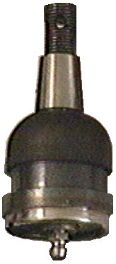
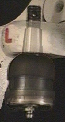
CONCERNS...?
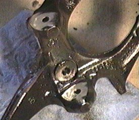
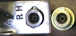
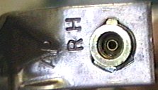
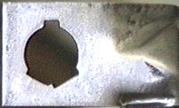
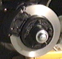
Concerns about suspension geometry can be settled by looking at the parts to be
used. Below is a picture of my original H-Body 4-lug components compared
to the S10 5-lug parts I installed. Notice that the difference of the
outside dimensions from the top of the upper balljoint boss to the bottom of
the lower balljoint boss is only 1/16" and the difference in the length of
the tie-rod arm is only 1/2". I prefer the S10/S15/Blazer parts
since the lug-nuts/studs are larger (stronger) and the steering knuckle on the
spindle is only 1/2" longer than the stock Monza piece whereas the G-Body
part is a full inch longer. Keep in mind that the S10 studs are metric
and will require size 12X1.5 lug nuts. For you racers, you will want to
get longer lug studs so they will protrude past your open lug nuts (length
depends on wheel thickness). NOTE: when using the adapters, you must use
1975 or later lower balljoints as the 1974 and earlier lower balljoints are too
small. All H-Body upper balljoints are the same size. Late model
balljoints are still available at your local parts store.
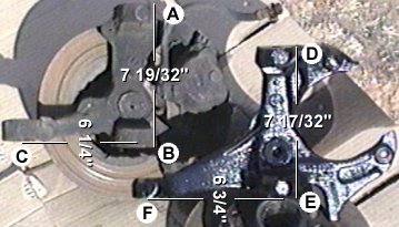
(H-Body [A to B] and the S10 [D to E])
As you can see, the S10 spindle
(lower right) is beefier than the H-Body piece.
The distance between balljoints is less on the S10 part, but the tie rod arm is
1/2" longer.
Remove the 4-Lug Equipment
|
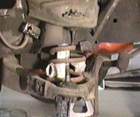
1. Set the parking brake, and break the lug nuts loose on the front tires. |
|
|
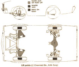
2. Lift and support the vehicle using a lift or a hydraulic jack and 4 jack-stands. The lift points are shown in the figure to the right. Place two jack- stands under the vehicle so that they contact the forward sub-frame, place a jack-stand between the lower balljoint and the outer tip of each lower control arm. If the vehicle still has an engine installed the jack-stands will support the lower control arm and the vehicle's weight should keep the coil-springs compressed. WARNING: If the vehicle doesn't have an engine installed you will need to compress the coil-springs. Coil-springs are very strong and may overcome the leverage causing the springs to violently break free after balljoint nut removal with possible injury or death resulting. Compress the coil springs before removing the balljoint nuts, and always use a safety chain to restrain the coil springs. |
|
|
3. Remove the lug nuts, front rims and tires. |
|
|
4. You won't need any of the factory equipment from the spindle out (including the old brake lines), so don't waste time removing the caliper and rotor. Using a 7/16ths line wrench, disconnect the brake line at the hard-line connection just behind the upper control arm. Using Vise-Grips, remove the brake line retaining clip from behind the brake line support bracket. Using a 1/2" socket, remove the brake line support bracket bolt (located just behind the bracket) and retain the bolt and bracket to be modified for use with the new brake lines. The brake line should now be free from the vehicle, but should still be attached to the caliper. |
|
|
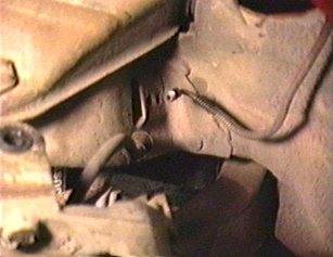
5. Remove the cotter pins and loosen the upper and lower balljoint nuts and the tie-rod end nut, with the balljoint nuts loosened, tap on the tie-rod end balljoint tip with a hammer. It should drop free with little effort, remove the nut and lower the tie-rod end. Tap on the upper balljoint tip and it should also easily break free, remove the nut and lift the upper control arm and swing the upper part of the spindle out from under the balljoint. Now the lower balljoint must be freed. Usually a balljoint fork is required to free the lower balljoint, especially since the lower control arm is being supported by one of the jackstands. So tapping it with a hammer will not be effective. Using a balljoint fork, separate the spindle from the lower balljoint. |
|
|
6. Carefully lift and remove the spindle assembly from the vehicle. Now would be a good time to replace any faulty front-end components since the next step involves prepping and installing the S10 (or GM G-Body) parts. Remember, before installing the modified spindles 1975 or later H-Body lower balljoints are required. Vega's lower balljoints are smaller and will not work. |
|
Preparing the S10 components
|
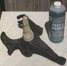
1. Disassemble the S10 components, clean them, and inspect them for wear, damage, cracks, and corrosion. Once the parts are cleaned and all rust is removed, use a treatment that will stop any rust that may have been missed and prep the surface for paint. |
|
|
|||||||||||||||||||||||||||||||||||||||||
|
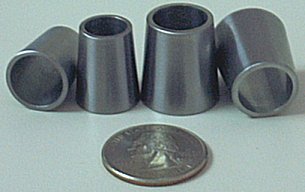
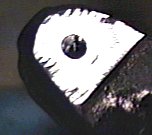
2. After the spindles have been painted and dried, it's time to install the balljoint adapters. The adapters are simple looking pieces made of mild heat treatable steel (heat-treated steel not required) that act as spacers between the balljoint and the larger hole of the S10 spindle. They eliminate the need to modify the control arms to accept the S10 balljoints. This makes this kit a solution that requires no modification of the control arms, saves you time and money, and allows restoration back to 4-lug if desired. The large adapters are for the lower balljoints and the small adapters are for the upper balljoints. |
|
|
|||||||||||||||||||||||||||||||||||||||||
|
3. Test fit the adapters first to ensure you have the correct adapter for the hole you're working on and that the corresponding balljoint on the car fits as well. Again, the lower adapters are the large ones and the upper adapters are smaller. Remember, you must use 1975 or later lower balljoints. Balljoints for earlier model H-Bodies are too small. Coat the adapter’s outer diameter with thread-lock, and then slip the adapter into place. DO NOT HAMMER THE ADAPTERS INTO POSITION. This may cause deformation of the adapter to occur. |
|
|
|||||||||||||||||||||||||||||||||||||||||
|
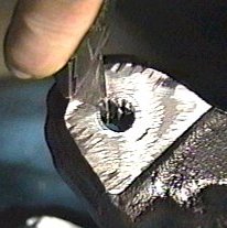
4. Once the adapters are installed, they should NOT protrude from the small side of each hole. This is because the adapters are designed to be short so that they don’t interfere with the threads of the balljoint or castle nut and will seat properly when the castle nut is torqued. However, because of the + or - 0.005” tolerance, they may protrude from or be countersunk into the large end of each hole. The adapters in this picture grossly exaggerate the condition for illustration purposes only. |
|
|
|||||||||||||||||||||||||||||||||||||||||
|
5. You may trim the protruding ends of the adapters so that they are flush with the spindles factory surfaces on each side of both ends (large end of each hole only). This will result in some flash inside the adapter hole. Using a utility knife or other suitable method remove the flash and bevel the sharp edges. |
|
|
|||||||||||||||||||||||||||||||||||||||||
|
|
|||||||||||||||||||||||||||||||||||||||||||
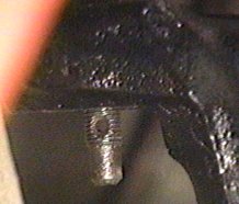
|
6. Touch-up the spindle ends with another coat of paint and allow to dry before installation. Installation is the reverse of removal. Tip - install the balljoints so that the cotter pin hole is easily accessible from either side of the spindle. That will make installing and removing the cotter pins much easier. |
|
|
|
|
|
|
|
|
|
|
|
|
|
|
|
|
|
|
|
|
|
|
|
|
|
|
|
|
|
|
|
|
|
|
|
|
|
|
|
|
|
|
|
Brakelines and Master Cylinder
|
1. Attaching the new brake hardware to your existing H-Body brake system is a challenge, but one easily tackled with some ingenuity. As can be seen here, the brake hose to brake line bracket has keyways in it. As luck would have it, the keyway is just the opposite of what it needs to be and swapping the brackets won't solve the problem as they are both keyed the same. The top-left picture shows the side that the brake hose must mate to (shown mated in the top-right picture). The lower-left picture shows the backside of the bracket with the factory Monza brake hose inserted into the keyed hole. The Monza brake hose is too short to reach the S10 brake caliper requiring a set of new 15" long hoses with an end shaped like the bottom-right image. I used a pair of Brakewareâ P/N 88624 hoses purchased from AutoZone for just $15.00 each. However, NAPA sells TruStopâ P/N 4136845, which doesn't require modification to fit the bracket. Both brake lines are originally designed for the 1976 Chevy Nova. So if you can't find these, ask for '76 Nova lines. |
|
|
2. Here you can see the difference between the keyways (viewed from the backside of the bracket) of the old hose (inserted) and the new Brakewareâ P/N 88624 hose. Remember, if using the TruStopâ P/N 4136845 lines, you shouldn't have to modify your brackets. |
|
|
3. Modify the bracket using a small fine toothed file. Note the new keyway on the bottom left (brake hose side of bracket shown). The right picture shows the side facing the brake hose with the new key at the 7 O'clock position. |
|
|
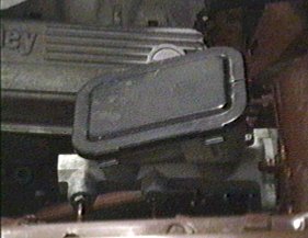
4. Once the brake lines are installed, you're ready for the master cylinder. I've been told later model H-Bodies (1976 and later) that came from the factory with vented front rotors have a larger master cylinder and it doesn't need to be swapped. If you do need to swap your master cylinder, the G-Body and S10 (or some F-Body) master cylinders are the best (as far as I can tell). But the G-Body reservoir will not work because it is tilted forward (see picture - lower right). So get an S10/S15/Blazer master cylinder with it's reservoir (see picture - upper right) or purchase the reservoir separately. Otherwise, you'll ruin the paint when the brake fluid spills out during servicing and you'll never get it FULL again. Don't forget to get the S10 proportioning valve as well or install an aftermarket adjustable proportioning valve or your brake bias will be incorrect resulting in malfunctioning brakes. NOTE: H-Bodies originally equipped with vented rotors (usually 1976 and later) are reported to have the correct brake proportioning. |
S10 Type
G-Body Type DO NOT USE! Notice how it's tilted forward |
|
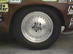
5.
The larger S10 front brakes will
greatly enhance your vehicle's braking ability. The discs are
3/4" dia. larger than the H-Body's and aftermarket S10 discs and
calipers are even larger. Mounting the 15" X 6" Centerlines equipped with 6.00-15L tires
leaves just barely enough room to turn the tires in the fender wells. |
|

Steering
Only the Vega Manual Gearbox is smaller and shorter than the others. The steering column shaft is at least 2 inches different in length. There is no way one could "make it fit". The Vega manual center link is different where it connects to the Pitman arm. The end is 1-1/2 longer and sets at a different height. For a Vega-to-Vega conversion, this will cause the center link to either rub on the oil pan, if you go power to manual, or rub on the K-frames if you go manual to power. Mine did, till I changed the center link. All the couplings are keyed, so they should only go together in one orientation. There are THREE H-body pitman arms. The CV uses the same pitman arm as V-6 and V-8 H-bodies with manual steering. All H-bodies with P/S use a second pitman arm. The third pitman arm is used on 140s w/o PS. Make sure you have the correct pitman arm.
The 1/2" longer steering arm on the S-10 spindles will affect the turning radius, and steering quickness (a fair amount slower). The whole steering mechanism (pitman arm, center link, etc.) will be forced to move through a significantly longer arc because of this additional 1/2" in steering arm length. The steering box internal stops will most likely not allow the rest of the steering to hit those external stops.
The S-10 spindles have longer tierod arms. It may rub at one point from lock to lock right when the Pitman is lined up with the steering box with the front wheels straight. You can't feel it in the steering wheel but it rubs enough to cause the tierod to deflect a slight amount. I used my die grinder to take off about a 16th of an inch off the centerlink to get it to go by without hitting but it’s still close.
When I changed my idler arm that there was an adjustment that you could do by turning the arm while holding the part that bolts to the frame that would effectively raises or lowers that end of the idler arm and centerlink. The objective is to have the centerlink level on both ends, you don't want one end higher than the other or it could screw up your geometry. This may be a possible reason why the centerlink is rubbing. If you just bolted the idler arm on the way it came out of the box without performing this adjustment this might cause rubbing.
How do I swap my non-tilt steering column for a tilt unit?
The columns interchange, but you'll need the right coupling for the steering box, and the ignition switch must be rotated 180 degrees. Any tilt column will work. Just make sure you get the column coupler shaft that connects to the steering gear box. The tilts I have found are on power steering cars. If you don't have power steering (I don't) you have to make a coupler from the upper part from a tilt column and the lower from the standard steering shaft. Different shaft lengths can be manipulated to get what you need in a column or steering gear box swap. I have a manual steering car that I transplanted a tilt column into. I took the manual column shaft and the tilt column short shaft and combined them. The columns are hollow and have a telescoping feature. You heat the shafts up with a propane torch and slide them apart. You then take the top and bottom halves that you want to keep and combine them. I relocated two of the alignment holes, and injected nylon hot glue from my wife's glue gun back into the column to fasten it back together, thus restoring the collapsing feature. Don't weld the column back together as you will be defeating the collapsing feature!" You could probably do the same for a power steering to manual steering or vice versa. All you really need is the shaft pieces. It makes it easier than finding the appropriate pieces, which can be hard to find especially in the case of a manual to tilt column swap as most tilt columns came in power cars.
Alternative Mounts
OK all, here is the scoop on how to retrofit a set of 68 327 Camaro motor mounts to your V8 Monza. However, there is one catch. First, you must be willing to hack up your original V8 motor mounts. If you don't want to do this then there are other options. Second, you must take your time doing what I will explain. Let's get started. You first need to have full access to your motor mounts (this means removing headers, etc. You then place your car on jack stands, making certain the car is level from side to side. Next, measure from the block (each side) to the floor, logging these measurements. Now, place a flat piece of wood on a jack and slightly lift on the engine at the oil pan. Unbolt the motor mounts from the mounting pads (not the block). Now, remove old mounts from engine block. Go to the auto parts store and purchase a set of 68 327 Camaro motor mounts ($10 each). Now comes the scary part. First, drill apart the 3 rivets that hold the flat plate of the block side of the motor mount and the clamshell that holds the rubber portion together. Separate the two halves, giving you better access to the loop of the mount. You are going to cut (with a steel cutoff wheel in a die grinder or drill motor) your original motor mounts at the "bend" on each leg where the leg bends going into the rubber portion of the mount (not the nut end of the leg). It is critical that you cut as close to the bend as possible. Be careful to not cut downward from the bend on the leg too far towards the welded nut end. You will need as much of these legs as you can get. Now, bolt the Camaro motor mounts to the block. Re-measure your distance from the block to the floor and match the height to your earlier measurements. NOTE: since your original mounts probably let your engine sag, you may wish to raise the measurement by 1/4" to 1/2" to get the motor where you want it. Next, bolt the cut off "legs" in their position on the motor mount pads (the pads on the unibody portion, not the block). CAUTION!!!! this next part is the most important part of all. Maneuver the legs into the proper position (install the bolts, but just finger tight) on the pads and line them up so that the holes in the sides of the Camaro motor mounts will provide the most "meat" on the legs to hold the motor once you drill the holes in the legs. So, to rephrase, you are using the "legs" of your original mounts, drilling holes in them to line up with the side holes in the Camaro motor mounts and using grade 8 or grade 5 bolts and lock washers to bolt it all together. The best way to get the markings on the insides of the "legs" of where to drill the holes is to use a 90 degree bent pick and scribe through the holes in the Camaro mounts onto the "legs" of your original mounts. Once you have the locations scribed of where you are going to drill the holes, simply unbolt the legs, drill the holes, put the legs back in place and bolt it all together. There you have it--simple, straightforward and cheap. However, if you are afraid to cut your V8 mounts ask yourself what is better: Driving with loose, floppy motor mounts or having new rubber motor mounts. Finally, for those of you who are concerned about the strength of this set up, I am running a 350 horse 350, with 3.73 gears, Auburn posi, 15" x 8 1/2" Centerlines on z rated tires and nothing and I mean nothing moves. This set up is the best thing I have done to my Monza. Also, I recommend that you put Energy Suspension's polygraphite transmission mount in while you are under the car. You will have to cut the bottom plate off of your original tranny mount and drill a 7/16" hole in this plate to bolt into the new Poly trans mount. Once all this is done your V8 hbody will be solid and secure.
Replacing the Stock Elbow with the F-Body 1LE Elbow
This method totally removes the baffle and replaces the stock elbow with the larger Camaro 1LE (non-air-conditioned) intake elbow. The 1LE elbow doesn't have the hole in top like the Impala does, and doesn't have the hole in the bottom like the air-conditioned Camaros and Firebirds have. The '94 elbow has no provision for the vent tube from the OptiSpark distributor, while the '95 has a connector in the top for it. The '94 can be modified to accept the vent hose by puncturing it on the bottom. The Camaro elbow is wider than the Impala elbow and can thus flow more air. They are slightly expensive since they include the MAT sensor. This method is recommended for those looking for maximum flow into their engines and are willing to pay the price to keep only GM parts in the engine.
Parts Required:
- A '94 or '95 non-air conditioned 1LE intake elbow. The list price is $80-$90 (the '94's are cheaper), but some dealers sell them for as much as $150. P/N 25147210 is the '94 1LE w/o vent nipple ($95.63 retail) and P/N 25147187 is the '95 1LE w/ vent nipple ($155 retail!).
Procedure (from Scott Mueller):
- Replace the stock elbow with the Camaro elbow, reconnecting all sensors and hoses.
- If the elbow is from a '94, you'll need to pierce it to insert the blue nipple for the OptiSpark vent. On the first rib from the throttle body, about 20deg to the driver's side from the bottom, use a drill bit just smaller than the blue vent tube elbow and bore a hole through the rib. You can then push the blue vent tube into the hole and hide "yet another vacuum tube" from view. You'll need to trim the vacuum tube to length (about three inches I think). When finished you'll have a factory looking intake elbow and a hidden distributor vent tube. Be sure to put it on the side of the elbow, not the bottom, so that moisture won't enter the distributor.