Converting a GM FWD Wiring Harness
for
Custom Turbo Buick Applications
LEGAL DISCLAIMER...Because "stuff happens"
These
instructions are a compilation of my experience in this modification. Your
experience may differ. I won't be liable for any damage to your car or
equipment, injury to persons, errors in judgment, or depletion of your
finances. You must possess a certain level of automobile electrical
knowledge and common sense to perform this modification. By using this
procedure the user accepts full responsibility for any damage or injury to
persons or property that may result. If you have any doubt, order a
custom aftermarket harness and have it installed by a professional!
Description or use of any manufacturer’s product does not constitute an
endorsement. If you find errors, have any suggestions, personal
experiences, or information you think would be useful here please e-mail me at denglish@ipapilot.org.
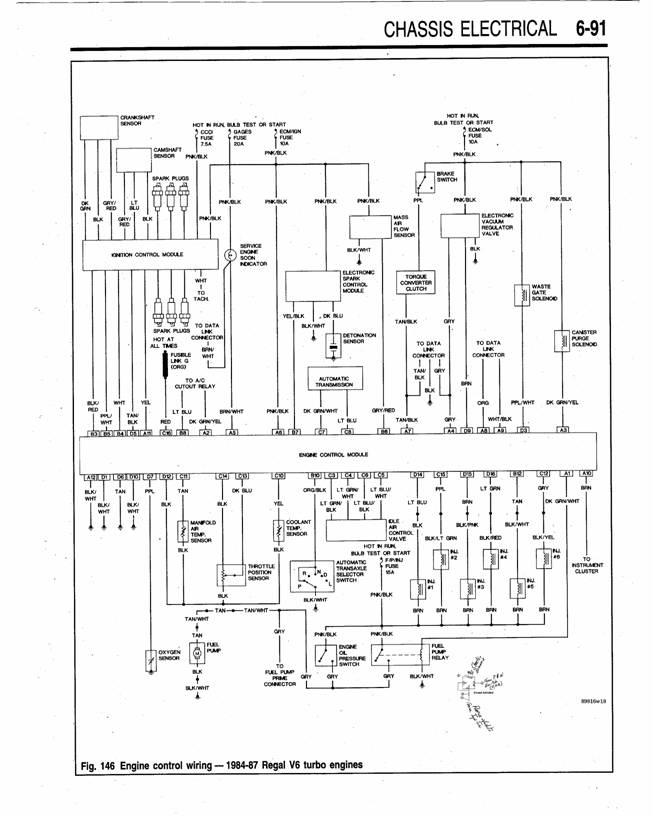
- Many mid-late ‘80’s GM FWD vehicles use the same ECM that was used in the ’86-’87 Turbo Buick T-Type Regals and Grand Nationals, and the ’89 Pontiac Turbo Trans Am; GM P/N 1227148.
- Because the ECM is the same, most of the wiring harness is very similar. Only minor modifications are required to make a wiring harness from one of the thousands of FWD Buick-V-6 powered vehicles work in a Turbo Buick application.
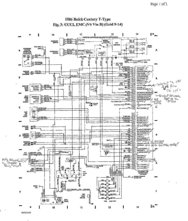
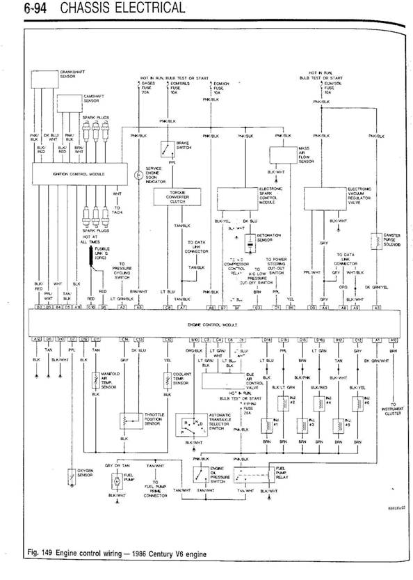
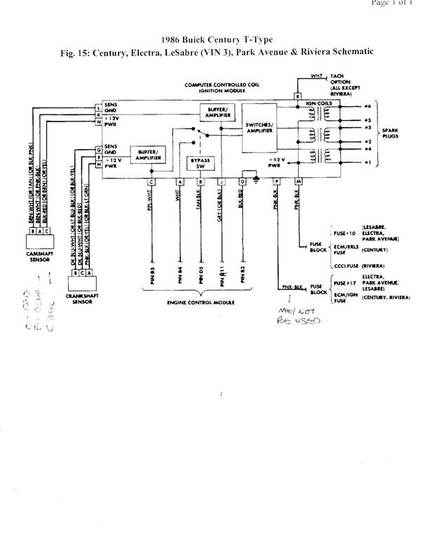
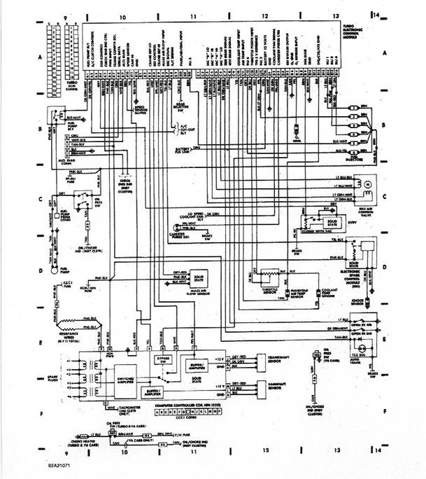
- I have provided the wiring diagrams I used for the modification. You will need a wiring diagram from the donor vehicle, which may require purchasing a Haynes or Chilton’s manual. Often, the information can be found at the public library.
- The biggest problem will be using wiring colors to identify the circuit. Some of the wire colors in the FWD vehicles are different than those for the GN harness; most notably the wires from the ignition module to the cam position sensor and crank position sensor.
- Even though the circuits are essentially the same,
some sensors used different connectors. These can either be
scavenged off other vehicles or purchased from
- Here’s what you will need to do the job:
- Wiring Diagrams—Examples are attached, but you may need to find them for your specific donor and application
- Donor Harness
- 150 Watt Soldering Iron with solder
- Heat Shrink Insulation
- Wire Crimp/Stripper/Cutter tool
- Utility Knife
- Small jeweler’s screwdriver(s)
- Assorted ring- or blade-type wire connectors
- Extra 12, 14 and 16 gauge wire
- Black electrical tape
- Masking tape or duct tape (for labels)
- Nylon wire ties
- Convoluted tubing
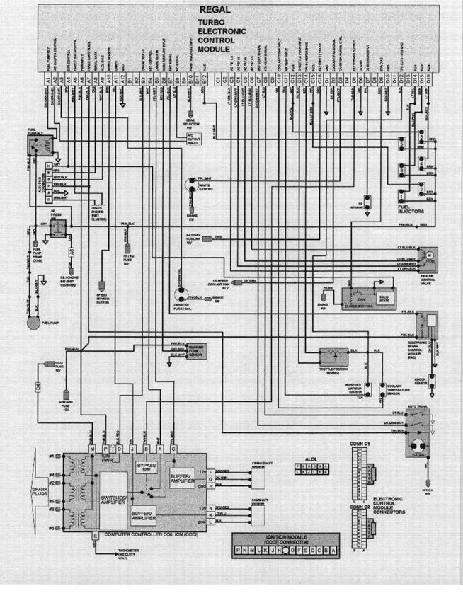
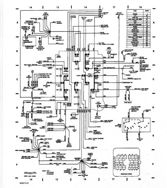
Wiring Diagrams
|
Fuel Injection ECM Pinouts |
|||||||||||||||||||||||||||||||||||||||||||||||||||||||||||||||||||||||||||||||||||||||||||||||||||||||||||||||||||||||||||||||||||||||||||||||||||||||||||||||||||||||||||||||||||||||||||||||||||||||||||||||||||||||||||||||||||||||||||||||||||||||||||||||||||||||||||||||||||||||||||||
| Scott Simpson | |||||||||||||||||||||||||||||||||||||||||||||||||||||||||||||||||||||||||||||||||||||||||||||||||||||||||||||||||||||||||||||||||||||||||||||||||||||||||||||||||||||||||||||||||||||||||||||||||||||||||||||||||||||||||||||||||||||||||||||||||||||||||||||||||||||||||||||||||||||||||||||
|
1986 & 1987 3.8 Liter Turbo Engine |
|||||||||||||||||||||||||||||||||||||||||||||||||||||||||||||||||||||||||||||||||||||||||||||||||||||||||||||||||||||||||||||||||||||||||||||||||||||||||||||||||||||||||||||||||||||||||||||||||||||||||||||||||||||||||||||||||||||||||||||||||||||||||||||||||||||||||||||||||||||||||||||
|
This ECM Chart is for use with a digital voltmeter to further aid in diagnosis. The voltages you get may vary due to low battery or other reasons, but should be close. The ECM has 2 connectors: 1 24-pin (A&B) and a 32-pin (C&D) The following conditions must be met before testing:
Notes:
|
|||||||||||||||||||||||||||||||||||||||||||||||||||||||||||||||||||||||||||||||||||||||||||||||||||||||||||||||||||||||||||||||||||||||||||||||||||||||||||||||||||||||||||||||||||||||||||||||||||||||||||||||||||||||||||||||||||||||||||||||||||||||||||||||||||||||||||||||||||||||||||||
|
Connector C100 |
|||||||||||||||||||||||||||||||||||||||||||||||||||||||||||||||||||||||||||||||||||||||||||||||||||||||||||||||||||||||||||||||||||||||||||||||||||||||||||||||||||||||||||||||||||||||||||||||||||||||||||||||||||||||||||||||||||||||||||||||||||||||||||||||||||||||||||||||||||||||||||||
|
|
|||||||||||||||||||||||||||||||||||||||||||||||||||||||||||||||||||||||||||||||||||||||||||||||||||||||||||||||||||||||||||||||||||||||||||||||||||||||||||||||||||||||||||||||||||||||||||||||||||||||||||||||||||||||||||||||||||||||||||||||||||||||||||||||||||||||||||||||||||||||||||||
|
Connector C437 |
|||||||||||||||||||||||||||||||||||||||||||||||||||||||||||||||||||||||||||||||||||||||||||||||||||||||||||||||||||||||||||||||||||||||||||||||||||||||||||||||||||||||||||||||||||||||||||||||||||||||||||||||||||||||||||||||||||||||||||||||||||||||||||||||||||||||||||||||||||||||||||||
|
|
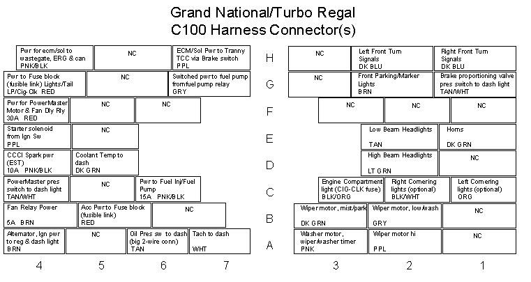
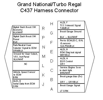
· Most of the FWD donor harness will be on the engine side of the firewall, but some of it will be on the interior, running from the ECM connectors to the ALDL, the VSS sensor, the Park/Neutral switch, the brake switch (for TCC cut-out), and Check Engine light. Some circuits will run from the engine/ECM wiring harness, through another Firewall bulkhead connector, and back to the interior of the donor car. These include wires to power various sensor circuits, such as the ECM/Inj circuit, ECM/EVRV circuit, CCC circuit, F/P Crank Circuit, and Tach. Most of these (except the Tach) will be a Pink/Black wire, and continue from the bulkhead connector to the fuse block inside the car. You can safely mark and cut these at the bulkhead connector because you are going to provide power to them from a separate relay/fuse block.
· Next, decide if you plan to keep the stock fan wiring and relays. They are set up much the same as on the ’86-’87 GN, with three relays to operate dual fans at low-speed and high speed. The ECM wiring harness will connect to the Fan Relay sub-harness by a green wire from Terminal D2 on the ECM connector. The stock fan wiring and relays can be used to activate your fan, or if you want to use an aftermarket electric fan relay, simply cut this wire near the low-speed fan control relay and mark it “fan control”. You can then wire it into the aftermarket relay.
· After you have pulled and removed the donor harness you will want to identify all the ground wires. Most of these can be attached to a common terminal either on the engine block itself or on the firewall provided a braided ground strap is also run between the engine block and firewall ground terminal. Normally, these will be solid black or black wires with a white stripe, and if you didn’t cut them they will have a ring-type terminal on the end.
· Now, let’s start modifying the harness to make it compatible with the GN ECM. The wire at terminal D3 on the FWD harness I used was for an A/C Low Pressure Switch input. You should re-label this wire Wastegate Control, as it will now go to the WG solenoid. Terminal D1 was empty on my donor harness. On the GN, there is a tan/white ground wire here. I don’t know why it is not black/white, but you will need to add this wire. I recommend carefully pulling the purple D11 wire out of the ECM connector and swapping it into the D1 cavity. You will need to remove the retainer cover from the ECM connector, then use a small jeweler’s screwdriver or straightened paper clip in the terminal hole on the ECM side to spring the terminal loose. Once you remove it, adjust the spring pin on the terminal and re-insert it into the D1 cavity, then re-assemble the connector. If you prefer, you can cut and splice a new black or brown/white wire close to the connector and attach a ring terminal so it will be easily identified as a ground wire.
· The B1 Memory Power wire shows as “not used” with the GN, and it can be safely removed using the same procedure described above.
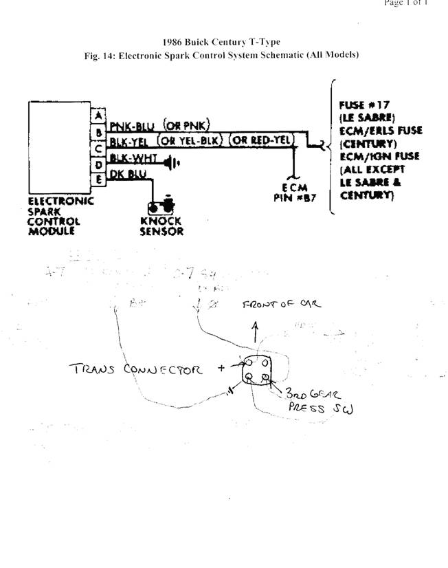
· You will need to add a dark green/white wire at ECM terminal C7 to provide a Third Gear signal from the transmission to the ECM. This wire continues to Pin C on the Torque Converter Control (TCC) connector. (On my car, I used a TH350C three speed transmission, so I spliced a short lead from C7 to the wire going to C8.)
·
I mentioned earlier that the color coding on the ignition module wiring
may be different on the donor harness than the color on the GN. Since you
will need to splice in a new Cam Position Sensor connector, it is very
important to verify the wires are correct. All connectors have a letter
code associated with the pins. It may be difficult to see, but it’s
there. The correct routing from the CCCI to the sensor is N to A, K to B,
and L to C. Similarly, the crank sensor is H to A, G to B, and F to
C. If you buy a
·
I also remember that the MAF sensor wiring was different on my donor
harness. I replaced the FWD connector with a stock GN MAF connector from
· You could tie into a pink or pink/black ignition hot on your car’s main fuse box to power the harness and sensors, but I used a 3-circuit Painless Wiring Circuit Boss kit to power the engine and ECM so as not to overload the stock wiring on my car. Hook a pink (ignition hot) wire from your car to the pink wire on the Circuit Boss. The circuit breaker in the kit should come off the positive battery terminal, and then go to the relay on the Circuit Boss block. The block should be grounded to your firewall.
· Now you have three wires (yellow, blue, and purple) available to hook up your modified harness. Look for all the pink/black wires on the GN harness. Trace them, and they should tie together in three bundles—
1. ECM/Ignition Circuit: the "P" pin on the ignition module, A5 Service Engine pin, A6 Ign/ECM pin, the B pin off the ESC, and the pink/black wire off the MAF sensor
2. ECM/Solenoid Circuit: the pink/black wire from the brake switch (or the purple wire from the transmission TCC connector-- it depends on how your harness was cut) the pink/black wire from the EVRV or EGR control, the pink/black wire from the WG solenoid, and the pink/black wire from the Canister Purge Solenoid;
3. Fuel Pump/Injector Circuit: the pink/black wire from the engine oil pressure switch, the pink/black wire from the fuel pump relay, and the pink/black wire from the fuel injector harness that ties into the brown wires to the injectors.
4. CCCI Circuit: from the "P" pin on the Ignition Module
· I tied the ECM/Ignition Circuit into the yellow wire on the Circuit Boss, ECM/Solenoid Circuit into the purple wire and Fuel Pump/Injector Circuit into the blue wire. I tied the CCCI Circuit to the pink wire on the Circuit Boss near the splice from your car. Finally, the red or orange wire from the C16 pin should go to a hot battery terminal-- put it on the battery side of the circuit breaker in the Painless kit.
· If you identified all the ground wires as described earlier, now would be a good time to ground your harness. Connect them to a bolt on the engine block, or use a remote firewall ground with a ground strap from the engine to a firewall terminal. If you start getting strange indications after hooking up your electronics, SUSPECT A BAD GROUND!!!
· Identify the wire from the fuel pump relay to power the electric fuel pump. This will either be a grey, tan, or a tan/white wire that is on the same lead from the relay as the fuel pump prime connector (The fuel pump prime connector on my FWD harness was a grey wire with a green connector.). Tie this wire into the existing stock wiring if your car already has an electric fuel pump, or run a 10-gauge wire from this wire to power the fuel pump. Alternatively, you can purchase a “Fuel Pump Hot Wire” kit from one of the many Turbo Buick vendors who sell them and use this wire to control the relay provided with the kit.
· The Orange/Black wire off ECM pin B10 will need to be tied into the Park/Neutral switch on your shifter. Ensure the other terminal on the Park/Neutral switch is grounded.
If you want to add a Park/Neutral starter cut-out circuit, you can add a relay to do this. Follow the diagram below to add this circuit.
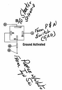
Park/Neutral Ignition Safety Cut-Out
· The Vehicle Speed Sensor wire from ECM pin A10 should be hooked up to either the stock Vehicle Speed Sensor Buffer in the dash, or an aftermarket 2-pulse VSS. I recommend the JTR Part #2PRS; a two-pulse square wave unit for all passenger car TBI installations, all computer controlled carbureted engines, and 1985-1989 TPI engines. Its output agrees to within 2 MPH on my speedometer according to my scan tool read-out. Remember to ground the other wire from the VSS to the body of the car.
· If you did not take the complete Check Engine and ALDL wiring, you will need to wire these back into the harness. Pin A of the ALDL goes to ground. Pin B should have a black/white wire from diagnostic test pin A9 on the ECM connector. Pin D should have a brown wire added that goes to the positive side of the Check Engine light. Another wire should go from ECM Pin A5 to the positive side of the light. The other terminal on the Check Engine light goes to ground. Pin E has an orange wire that connects to ECM pin A8 for serial data. Pin F is a tan/black wire that is spliced into the tan/black wire running from ECM Pin A7 to the transmission Torque Converter Control connector. Make sure you have enough wire to run the ALDL connector to a convenient location inside the car.
· The Torque Converter Control connector should have four wires. Run a purple 12-gauge wire from the purple wire on the Circuit Boss to a 4-or 6- prong brake switch. This wire goes to one of the terminal on the switch that is normally closed when the brake is not depressed. Continue with another purple wire from the other terminal to Pin A on the TCC connector. (This is to break the circuit when the brake pedal is depressed.) Pin B has a light blue wire that goes to ECM Pin C8 for the 4th Gear signal, Pin C is a dark green/white wire that was added to the FWD harness at ECM pin C7. Pin D has the other end of the tan/black wire that comes off ECM Pin A7 and also splices into the F terminal on the ALDL (described above). Note that the wires from pin B and C connect to normally closed pressure switches in the 2004R transmission. When the transmission is not in third or fourth gear, the pressure switch ECM sees the circuit lose power, and determines that the transmission is in that gear. The stock ECM uses this signal to adjust timing and fueling in third and fourth gear. These wires do NOT affect torque converter lock-up; that is still controlled by grounding the circuit off A7.
That’s it! You have successfully converted a FWD harness to work with the ’86-87 Turbo Buick ECM and sensor set-up. You can now further modify the harness to the proper length for your application by cutting, splicing, soldering, and shrink-tubing as required. When you are finished, use convoluted tubing to protect and dress up your harness. And to think, you did it yourself and saved hundreds of dollars in the process!
E-mail me at denglish@ipapilot.org if you have questions.