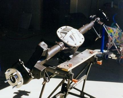
REAR END FROM S-10
The 3-link rear suspension setup in all Monzas and post-'75 Vegas is very good. It is similar to the H-Body configuration and the Third and Fourth Generation F-Body designs. The Camaro/Firebird setup from 1982 on was designed around the H-Body configuration. With that said, you can't find a much better setup for all-around performance than the stock configuration offered by the ’75 and later H-Bodies.
Be aware not all ’75 and later H-body rear-ends are the 7.5” diameter type. From 1976-1977, the Vega used either a 6.5” or a 7.5” rear end. From 1978 on, all H-bodies were 7.5” diameter. See the http://h-body.org/ FAQ website for details on where to find rear axle codes and matching ring gear diameters.
If you are putting out more horsepower than stock, it is probably a good idea to update the rear end in your H-Body. The stock 6.5" rear end in a Vega is a bomb waiting to go off. While the 7.5" found in Monzas and others is better, it probably won't hold up very well over 300 hp.
You can use the rear end out of an S-10 Truck. Try to find a 4-cyl truck since they usually have a 4.11 gear and sometimes a posi unit. The S-10 rear will hold up pretty well until you start making mega-power. You will have to weld all the brackets from the Vega rear to the S-10 rear. Because the S-10 rear is actually 1" narrower than the Vega rear, you can work with backspacing to get a 9-10" tire in the fender without tubs! You also get the five-lug pattern with the S-10 rear.
It is possible to use just the axles, ring, and pinion from an S-10 rear end with some changes to different bearings. Instead of using the whole rear end from an S-10, you can also just use the axles from an early '80's 2wd S-10 You can only use 2-wheel drive Chevy S-10 and Blazer axles for a 5-lug upgrade. The axles are the same spline (26 spline) and are only 1/16" shorter than the stock Vega axles. This makes a 5-bolt swap easy. Grab the larger drums and backing plates from the S-10 as well. Besides being larger, they are often finned (better cooling) and some of them are aluminum (lighter). This swap will only work with '76 and up 7.5" rear ends.
In some cases the shorter axles result in the rear brake drums (also 5-lug) rubbing against the rear backing plates (dust covers) around the edge where the drum meets the back cover. The backing plates may have to have about 1/16" shaved of the lip facing the drum to prevent rubbing. Mine do not rub, but if you find that yours do just remove 1/16th inch from the edge of the backplates. To do this, I would suggest scribing the backplates 1/16th inch in and using a handheld grinder, remove the excess metal. Then smooth the edge with either a file or sandpaper. NOTE: 1975 and earlier vehicles have 9" diameter by 1" wide brakes and therefore a smaller backing plate. Later model (1976 to 1980) backing plates will be required for this modification.
The 7.5" Chevy S-10 gears will fit the H-Body case, but the main problem is that, in the differential case, the hole for the pinion bearing is smaller in the H-body differential than in other GM 10-bolt differentials. You can either get a machine shop to enlarge this hole or use a special pinion bearing and race.
You’ll need; S-10 gears, S-10 posi unit (if it’s posi), and
S-10 axles (2 wheel drive only!) S-10 rear end yoke, S-10 drums (if you use the
S-10 axles). If you reuse the Vega axles, check if the carrier of the
S-10 is a 26-spline unit. The S-10 pinion gear requires Timken bearing
#16143, Timken bearing race #16283, and National seal #8610, S-10 pinion yoke,
and "Combination" U-joint (Dana #5-3022X). As with most all
gear sets a specific gear carrier is required for a specific range of gear
sizes, so the carrier must be the correct series for the gear set that you
want. In other words, you need to know what series the carrier is or
what gears were installed on it from the factory. A
2-series carrier fits 3.08 and numerically lower gears (3.08, 2.93, 2.73, 2.56,
and 2.29), while a 3-series carrier fits 3.23 and numerically higher
gears (3.23, 3.42, 3.73, and 4.10). The exception to this is if you
purchase custom gears specifically made to fit your specific carrier (i.e. you
can buy 3.23, 3.42, 3.73, 4.10, and 4.56 gears to fit the 2-series carrier).
If
you are at all performance minded, you will probably
want to have a positraction unit in your H-Body.
Stock posi rear ends for these cars are actually
quite abundant, but can sometimes be pricey. You can upgrade to a new or
different posi carrier by getting a 26-spline carrier
of the right series for your gears
So, the list is:
- Enlarge
pinion hole in differential and use S-10 bearing, race, and seal
-OR-
Use these non-factory parts:
Timkin bearing #16143,
Timkin bearing race #16283, and
National seal #8610. - 7.5" gear set with pinion
- New carrier if the new gears won't fit your current carrier (see 3.10)
- S-10 rear end yoke
- "Combination" U-joint (Dana #5-3022X) to mate the S-10 yoke with your stock driveshaft
NOTE: Installing new gears requires setting the proper pinion depth and carrier position. Doing this wrong will destroy your gears. Even the most die-hard shade tree mechanics leave this to a professional. If you want to try it anyway, this is the basic procedure and tips from Robert (twelve_second_vega): "When you pull the carrier, mark the shims on the side of each bearing. They are cast iron and must be handled with care. Put a new crush sleeve on the pinion and install it in your 7.5" housing. Set the preload (about 10 inch pounds with used bearings) and set the carrier in place. Gently tap the shims you took out into place with a PLASTIC hammer and torque the caps. Only once did a gearset need to be reset. 99% of the time, you can just throw them in and go. If the backlash is off (.005" - .008" with used gears) you will need different shims. Subtract the amount you need (in backlash reduction) from the right shim to move the ring gear deeper into the pinion. BE SURE to add this SAME AMOUNT to the opposite shim. You MUST maintain the preload on the side bearings. When properly set-up, you will have to pry the carrier out of the housing and putting shims back in should not be easy either."
Ring/Pinion Swap Specs
(Turn the S-10/F-body
pinion down .060")
H-body pinion O.D. (rear bearing): 1.3755”
(front bearing): 1.1875”
S-10 pinion O.D. (rear bearing): 1.975”
(front bearing): 1.1875”
Cover gasket: Victor #P2782 (
Bearings (axle): JM14070 (?); Torrington DB67309; NAPA R1563-TAV
Seals (axle):
Bearings: (pinion, front, H-body & S-10): NDH
#M86649A; John Deere AR94761
(pinion, rear, H-body): Timken
#HM88649A
(pinion, rear, S-10, stock): Timken #HM89249
Races: (pinion, front, Buick & S-10): HDH #M86610CJ
(pinion, rear, H-body): Timken #HM88610A
(pinion, rear, S-10, stock): Timken #HM89210
Seal (pinion): National #8610
Differential carrier bearings: Timken #LM501349
Differential races: Timken #LM501314
S-10 rear axle ratio Info
GU4=3.08
GU5=3.23
GU6=3.42
GT4=3.73
GT5=4.10
HC4=4.56
G80 - locking differential
GM 7.5”
Year Application LUG SP Length Side OEM # WCD #
82-90 S-10 OR BLAZER 2WD 5 26 26 9/16” B 14030355 AXE14030355
88-90 S-10 2WD 7.625 5 28 26 9/16” B 26009534 AXE26009534
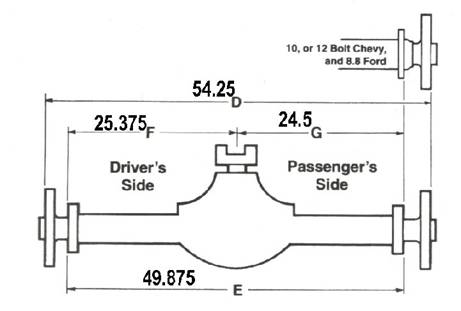
Vega/Monza Rear End Replacement Alternatives
The Ford
Ranger and Explorer with the 8.8" rear ends are only 51 "
axle flange to flange. The
Plus, these are littering the wrecking yards-- here in
REAR DISK BRAKES
Option One: Rear disk brakes
from the '80 Cadillac Eldorado. The rear
calipers, rotors and brackets can be adapted to a
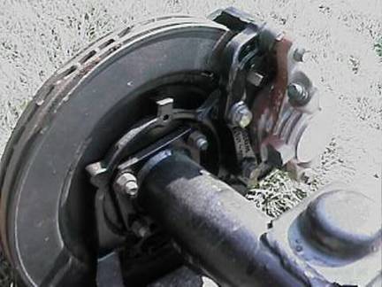
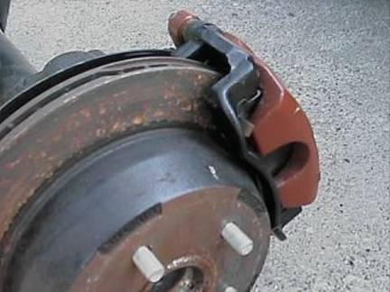
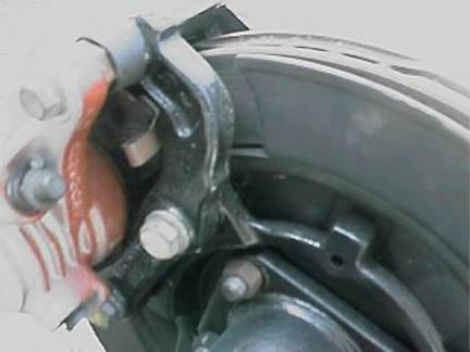
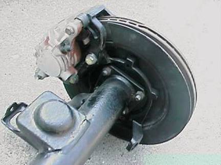
Option Two: Any '98 and newer Blazer, Bravada, etc. should have the parts to convert a 7.5” H-body rear end to rear disk brakes. The whole package: rotors, brackets, calipers, etc. bolt onto the H-body housing. The problem is the axle length is a little off. Plus, depending on the posi unit, there are different axle spline setups. You can order custom axle shafts from Moser Engineering to correct the length so the axle hub does not rub on the backing plate and the rotor and caliper line up correctly. The axles cost about $315 for the pair.
Standard S-10 axles are 26.9”
long. The custom axles are 27.1 inches from the end of the button to the
wheel flange. K=25.85, C=27.1, A=2.780, flange diameter 6.115, B=1.250,
H= 1.395. The axle length had to change because the Vega housing was
slightly different in length than the Blazer housing.
Also the rotor hat thickness is 0.275 inch which is a lot thicker than the drum
flange.
'98 and newer Camaro and Blazer share the new brakes with aluminum calipers and separate drum style parking brake. The rear caliper pistons are 1.900-inch diameter (38 mm). When you connect the brake lines to the rear calipers, make sure you use some short flex hose because the caliper moves relative to the axle. The best method is to use hard lines from the brake hose T to each end of the axle and weld a small bracket to hold the line. Then use about 6 inches of flex line to the caliper. This flex line will have a banjo fitting on the end and attach right to the caliper with a hollow bolt. Parking brake cables can be a problem. The F-body cables are too long, but criss-crossing them will take up enough length to allow them to work under the h-body.
How to build a better 10-bolt
I have always had a problem with the rear axle that came with my Trans Am: Known as RPO Code GT4, my original axle assembly came equipped with ten-inch rear rotors, coupled to 26-spline axles that were splined to an Eaton Guv-lock differential with a 7.5-inch 3.73:1 gearset. Now I imagine that this was an acceptable performance piece when the car was new, but with only 39,000 miles on the car, the clutches had already worn out. This becomes a problem with the Eaton unit, as the system will free-wheel like an open differential then lock solid with a bang. I lived with this malfunctioning differential for 90,000 miles! Since I was going to race this year, the LAST thing I wanted to happen was an unexpected lockup of the differential. It upsets the whole suspension and will quickly send you into a spin. It usually happens in conjunction with a hard upshift. Another problem with the GT4 is the original RPO J65 rear disk brakes: They have a faulty spring inside the piston that causes them to retract from the brake rotor. This results in excessive pedal travel, and no emergency brakes. Mine were corrected with a set of revised pistons from GM, but when I broke off a bleeder screw in the left caliper, I knew it was time to update.
My goal is to design a rear axle assembly that will hold up to about 400 horsepower. I looked at buying a 12-bolt, but parts are too expensive and hard to find. I looked at getting a Dana 44, but they were non-existent. A Ford 9-inch has alignment problems, and is easily $1500 for an entry-level assembly. What I settled on is the only solution that costs under a thousand dollars: A 10-bolt that uses the Gleason/Torsen heavy-duty Torsen differential, and aftermarket axles.
10-bolt Performance
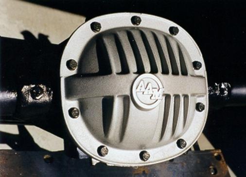
The Torsen heavy-duty differential is a unit that is currently being sold in the 1999 Pontiac SLP Firehawk. The LS-1 based Firehawk outputs about 345 rear-wheel horsepower, and offers a warranty to boot. Therefore, a goal for a 400-horsepower capable 10-bolt seems attainable with this differential. Research indicated that the Torsen is a direct bolt in to any 3-series 10-bolt carrier. Thus, the Torsen should be able to fit in my 1984 GT4 axle housing. Unfortunately, the GT4, being a pre-1989 axle, uses 26 spline axles whereas the Torsen employs 28-spline axles. Therefore, a new set of axles is in order. For these axles, I called Greg Moser of Moser Engineering. Moser Engineering can cut a set of 28-spline axles for the third-generation F-car or an H-body which are much more capable of handling the high-torque demands of a performance application. Thus, the Moser axles were chosen in favor of stock 28-spline axles from a junkyard. There have been reports of broken OEM axles squirting out onto the racetrack and I want to avoid this possibility. The Torsen heavy-duty differential was purchased through SLP-Performance on their Internet specials page. SLP offers two different differentials: An OEM take-off version, and the heavy-duty version that they installed in the 1999 Firehawk. The OEM is a real bargain, being virtually brand new, and already sporting bearings. Bearings cost $25 or more per pair anyway, so this is a good deal. The heavy-duty version is brand new, without bearings, but comes with a cast aluminum differential cover from American Axle and Machining (AAM). The Torsen differentials are designed for use in a 3-series carrier.
AAM Oil-cooling Differential Cover
This cover has a patented oil cooler cast inside it. I saw a lexan version of this cover in action at the 1997 SAE International congress--- Very snazzy. It catches gear oil as it is flung off the ring gear, and channels it through passages in the differential cover to the holes on either side of the differential case: These holes, normally used for case spreading, open up into the axle tubes on the other side of the differential bearings. The oil is dumped into the axle tubes, where it flows both to the load bearing at the wheels, and back into the differential case. Thus, your axle tubes become a method with which excess heat is drawn out of the oil. The AAM cover is also nearly half an inch thick at the mounting flanges, which should greatly increase the rigidity of the axle assembly. This should further increase reliability of the gearing.
One note: Mike Galda has just informed me that SLP is now shipping a
template that shows some grinding operations that you need to perform before
installing the differential. You need to grind a drain-back path for the oil.
I had a conversation with
In any event,
- Use Redline Synthetic shockproof geal oil.
- Weld the axle tubes all the way around, where they go into the housing to increase strength of the housing. The factory only used 2 spot welds here.
- Use a Zytanium cross pin. It is available in the Year One Next Generation catalog for $28.
- Use a solid bearing spacer instead of a crush sleeve. It costs about $20 from Ratech engineering
Related links:
Moser Engineering: Custom Axles
http://www.partsgm.com/
http://www.auburngear.com/
http://www.slpeng.com/
http://www.spohn.net/index.html
http://www.richmondgear.com/home.html
http://www.summitracing.com/
Zexel-Torsen how-to install
Zexel-Torsen how-to install
By HuTcH at Sun, 2006-04-09 15:03 | Drivetrain
Before you try doing this yourself, you need to read and decide if you are equipped, capable and willing. If not, you’ll save time, sweat and heartache if you pay a competent rear end professional to handle it. On the other hand, doing it yourself is the only way to really learn how.
Much of this information is applicable to differentials in general, but most is specific to the installation of the Zexel-Torsen limited slip carrier into GM 7.5” or 7.625” rear differentials with 3.23 or numerically higher gears and 28 spline axles. Most ’89 and up GM models have 28 spline axles. However GM did use a few leftover 26 spline axles after ’89, mostly in 2.2s and 2.8s. If your vehicle is near the ’89 changeover date check to be sure. If you have 26 spline axles you can purchase a set of 28 spline axles and still do the install.
Ok, are you ready to get sweat, greasy and possibly frustrated while installing your Zexel limited slip carrier, AKA Posi-Traction?
If so, loosen the 13mm-1/2” cover bolts and drain the gear oil into a suitable container. Jack or lift the rear end after loosening the rear wheel lug nuts. Securely support the vehicle as high as you can on appropriate jack stands. Remove the rear wheels. Remove the brake drums by tapping firmly around the rear edge while pulling outward.
Remove the differential cover and rotate the carrier until you have access to remove the 10mm-5/16” pinion shaft retaining bolt (use a 6 point socket to avoid rounding it off). You can now remove the pinion shaft that slides between the ends of the axles and keeps them from moving inward. Gently push one axle in to remove the large C-clip that secures the axle from moving outward. Carefully slide the axle out of the axle tube so as not to damage the outer axle bearing. Use a clean rag to wipe excess oil off as you withdraw it. Push in the other axle to remove it’s C-clip and carefully slide it out.
Since you have the axles out, go ahead and replace the axle oil seals located at the end of each axle tube. These seals are inexpensive and may start leaking as mileage increases. It’s easier to pull the seals out with a seal removal tool, but you can use the tip end of the axle. Be careful not to damage the bearings or sealing surfaces on the ends of the axle tubes. You’ll get a bit more differential fluid draining out of the axle tubes when you remove these seals. Be sure to collect it in your drain pan. If you have high mileage you should consider replacing the axle bearings also. You’ll need a slide hammer and a bearing removal tool that is able to pull from behind the seal. You may need to obtain the axle housing code to get the correct P/N seals and bearings. The axle housing code is stamped on the front of the passenger side axle tube, between the pumpkin and brake backing plate. Insert new seals and fully seat them by pounding them in flush with a large socket.
Ok! Back to the carrier removal. On each side of the carrier there is a main end cap secured over the carrier bearing races by two 16mm bolts. Mark the caps so they can be returned to their original location. Remove and set aside the four bolts and end caps. The carrier can now be removed from the differential housing, but first examine either end of the carrier and you will see shims wedged between the bearing races and differential housing. They are used to pre-load the carrier bearings and adjust the position of the ring gear for proper backlash.
Keep an eye on the shims when you pull the carrier out so you’ll be able to relocate them in their original locations. You will use these shims or new ones close to the same thickness as a starting point for proper backlash adjustment. If your rear end is in reasonably good shape, and you are just swapping in the Zexel carrier and using your old gears, you may get lucky and backlash will remain within the specification limits of .006” - .010”, but don’t count on it. That’s why you bought an install kit complete with varying thickness shims.
You’ll need a pry bar or bars and block of wood to coax the carrier out of the differential housing. You can use the 3lb. dead blow hammer or sledge to bang the carrier housing while you pry to get it started. Be careful not to damage the gasket-sealing surface of the differential housing or the ring gear. The bearing races, tapered metal rings that cover the carrier bearings, may fall off as the carrier comes out. They set over the bearings on either end of the carrier and are held in place when the carrier is installed and shimmed. You’re going to replace both of these inexpensive bearing races with new ones. Consider it cheap insurance to protect the like new bearings which are already pressed into both ends of the Zexel unit.
To transfer the ring gear YOU WILL NEED TO USE A BENCH VICE to hold it while you remove the 19mm-3/4" bolts that secure it to the OEM carrier. (*IMPORTANT NOTE: THESE BOLTS ARE REVERSE THREAD.) Cushion the carrier with a thick towel while mounting in the vice. If you haven’t removed the rectangular pinion block from the middle of the Zexel unit, do so now. This metal slab will slide in between the ends of the axles to keep them pushed out the same way the large cylindrical pinion shaft in the old carrier did. (NOTE: If you are running larger than 3.42 ring and pinion gears you may have to machine or file a couple grooves in the pinion block to slide it past the ring gear teeth later in the install procedure). Be sure to clean the ring gear and all bolts before installing it on the Zexel carrier. If the bolts are in good condition you can reuse them or use new high quality bolts. The old OEM bolts are better than cheap after market ones. Mount the Zexel into the vice and transfer the ring gear. Install the REVERSE THREAD 19mm bolts using Locktite and torque to 90ft.lbs. Torque the bolts in a couple stages while moving across and around the ring gear in a star pattern.
Now with the carrier out, it’s time to thoroughly clean the differential housing. Remove gasket material from the sealing surface and wash out the housing with clean solvent. Check all of the oil passages and grooves to make certain that there are no metal particles or dirt remaining.
You’re now ready to install the Zexel carrier into the clean differential housing. Apply clean gear oil to both carrier bearings. You don’t need to pack them with grease. Position the carrier with the new bearing races in place and shim the left side first. While holding the assembly in place shim the right side (an assistant will make it easier).
Clean and re-install the two carrier end caps in their original location over the bearing races. Torque the 16mm bolts to 50-60ft.lbs. Use Locktite on all bolts in final assembly.
Now carefully slide the axles back in taking care not to damage the lips of the seal and insert the C-clip into the retaining groove. Pull the axle back out to seat the C-clip in the counter-bore of the side gear. Clean and insert the rectangular pinion block between the ends of the axles. Tap it in lightly to seat it, don’t force it. If it resist insertion pull the axles outward while rotating slightly back and forth to be sure they are seated correctly. Locktite and torque the retaining bolt. Rotate the drive shaft to make sure everything is meshed correctly and the assembly rotates smoothly.
Apply a thin bead of gasket sealing compound around the cover and position the gasket onto it. Install the cover with gasket and torque the 13mm bolts to 10-15ft.lbs, again moving in a side to side sequence around the cover. Fill the differential with fresh gear oil to the bottom of the fill hole. Check for any leaks around the differential. Re-mount the brake drums and wheels, lower the vehicle and go for a test drive. Check the differential fluid level again on level ground after your test drive since some of the gear oil may have flowed back into the axle tubes. Congratulations, you now have two legs!
Here
is some basic differential terminology you should learn.
Flank – the bottom area of the ring gear that the gear teeth rise from. Also
called the root
Face – the top flat surface of each gear tooth also called the top land
Drive – the convex side of the ring gear teeth which the pinion contacts to
drive the ring gear
Coast – the concave side of the ring gear teeth opposite the drive, also
contacted by pinion gear
Heel – the outer edge of the ring gear
Toe – the inner edge of the ring gear
Pinion depth – the position at which the pinion contacts the ring gear teeth
between the face and flank
Pattern – the “footprint” where the pinion gear contacts the drive and coast
sides of the ring gear teeth (viewed by use of gear marking compound)
Backlash – the amount of free movement of the ring gear with the pinion held
fixed in place
Pre-load – the initial amount of force applied to the races upon the bearings
When
working on a differential there are four basic adjustments. In order of
importance they are:
1. Pinion Depth
2. Pinion Bearing Pre-load
3. Backlash
4. Carrier Bearing Pre-load
Be aware that adjustments of pinion depth, pre-load
and backlash effect each other. When you change one you must re-check the
others. Therefore it’s important to understand that for a correct install you
may have to remove the carrier several times to make the necessary adjustments,
indicated by the pattern and backlash measurements, to achieve proper
alignment.
Before you can adjust pinion dept you must set backlash. The best way to obtain backlash reading is with a dial indicator. You should be able to get a close indication of initial pinion depth if the backlash is within, or very close to the .006” - .010” specification. On most ring and pinion sets backlash will change about 0.007” for each 0.010” that the carrier is moved. Therefore if you need to decrease the backlash by 0.007”, move the carrier 0.010” closer to the pinion by shimming the left side. If you need to increase the backlash by 0.007”, move the carrier 0.010” farther away from the pinion by shimming the right side. Use a pencil and paper to keep notes of shim combinations and backlash. A calculator might also come in handy.
After setting the backlash you can check pinion depth. Do this by brushing three or four of the ring gear teeth with a moderate coat of compound in two locations on the ring gear. Rotate the ring gear past the pinion gear four or five times to print a good pattern. The gear marking compound will show a clear pattern of pinion contact on the ring.
The pattern you’re looking to achieve should be oval in shape and centered between the face and flank on the drive and coast side of the ring gear teeth. There should be an area of no contact below the face and above the heel on both sides. It would be ideal if the pattern was also centered between the heel and toe of the ring gear, but that is not necessary. The only part of the pattern that helps set the pinion depth correctly is the contact position between the face and flank of the teeth, regardless of the location concerning heel and toe. I’ll say it again; if the contact pattern is towards the heel or the toe of the ring gear teeth ignore that and look only at the position from face to flank. In most cases an ideal heel to toe pattern can not be achieved anyway. Trying to make adjustments to get a pattern that is centered from heel to toe will usually lead to frustration and a noisy gear set. The position of the pinion bearing bore in the housing and housing alignment affects the pattern from heel to toe and can not be corrected without machine work. So once again, a contact pattern that is centered from face to flank on the drive and coast side always indicates correct pinion depth even if the pattern can’t be centered from heel to toe.
If the contact pattern is towards the face of the ring gear teeth then the pinion is too far away from the ring gear. To correct it the pinion needs to be moved towards the ring gear with a thicker shim to position it closer to the ring gear centerline. If the contact pattern is towards the flank of the ring gear teeth then the pinion is too close to the ring gear. To correct it the pinion needs to be moved away from the ring gear centerline with a thinner shim. The shim is located between the gear and rear bearing.
If the backlash is within spec but the pinion depth is not correct you match-mark the driveshaft to the pinion flange and remove the driveshaft and suspend it with wire out of the way on something like the exhaust pipe. Match-mark the pinion flange, pinion shaft and nut (if you’re reusing the nut). Now check the bearing pre-load using an inch-pound torque wrench and record it before disassembly. The pre-load is the torque required to just begin turning the pinion shaft.
To remove the pinion nut and washer you will need to use a special flange holding tool or breaker bar to hold the flange in place while you loosen the nut. You may also want to install the cover loosely with a couple bolts so the pinion doesn't fall out. With the nut and washer off use a two-jaw puller to withdraw the flange by placing the two jaws on the backside of the flange and the puller screw on the pinion. Examine the sealing surfaces of the flange for nicks or gouges. Replace the flange if it's damaged. Use a blunt chisel to remove the pinion oil seal, being careful not to damage the carrier housing. The pinion can now be removed from inside the carrier case to replace the bearings, races, correct thickness shim and crush sleeve. It’s easiest to assemble the pinion without a crush sleeve until the correct pinion depth has been established. Install the new pinion oil seal. When initially installing the pinion slowly tighten the pinion nut until the pre-load is within the assembly specifications of 12-15 in. lbs. on a new pinion gear and 6-7 in. lbs. on a used pinion.
Understand
this is the hard way to set pinion depth without the six or seven special jigs,
and guage a GM tech has available. They can simple
install the various jigs and get a reading on the guage
that translates into the correct thickness shim required.
When changing the pinion depth always make large changes until the pattern is
close. Consider 0.005” to 0.015” to be a large change and 0.002” to 0.004” to
be a small change. Changes of 0.005” to 0.008” or more will lead to the correct
pattern faster than small changes will. If you move the pinion too far and the
pattern changes from one extreme to the other then you know that the correct
pattern is somewhere between the two extremes. Once you get close to the
correct pinion depth make smaller changes until the pattern is centered between
the face and the flank of the ring gear teeth. After the backlash and pinion
depth are set remove the carrier and set the final pinion bearing pre-load of
12-15 in. lbs. on new pinion gear and 6-7 in. lbs. on a used pinion. Use a new
crush sleeve for final assembly. Use oil on the pinion nut washer surface
during all assemblies and red Loctite on the pinion
nut threads during the final assembly. The oil on the washer surface helps the
nut turn easier while it is being tightened and the red Loctite
helps keep it tight.
On a crush sleeve design differential it usually takes between 300 and 400 foot pounds of torque to crush the crush sleeve. Use a large breaker bar and or very strong air operated impact wrenches to crush the crush sleeve. Proceed very slowly so that you get it right the first time. The pinion preload will be zero until the bearings contact the races. When the bearings contact the races the preload will increase very quickly. Take plenty of time to set the preload carefully so that the bearings will have a long life. If the crush sleeve is over crushed and the pinion bearing preload exceeds the specified allowable range the only solution that I know of is to install another new crush sleeve and start over. After reaching the correct pre-load, moderately tap both ends of the pinion to seat the bearings, races and yoke. Be careful not to hit the pinion so hard that it damages the bearings. After “seating” the pinion check the pre-load again to make certain that it is correct.
After setting the pinion depth, backlash, and pinion bearing pre-load it’s time to set the carrier bearing pre-load. During the original set-up you set the backlash with very little carrier bearing pre-load. Now set correct pre-load by inserting equal thickness shims to each side. Make it fairly tight, as tight as you can without damaging the shims while driving them in. If the pre-load is close and the backlash is wide, add shims to the left side. This increases the carrier bearing pre-load and decreases the backlash at the same time. If the pre-load is close and the backlash is too tight, add shims to the right side. This increases both the carrier bearing pre-oad and the backlash at the same time.
Now that the pinion depth, pinion bearing preload, backlash, and carrier bearing preload are set recheck the pattern once more to be certain that everything is perfect before final assembly.
All new gear sets require a break-in period to prevent damage from overheating. After driving the first 15 or 20 miles it is best to let the differential cool before proceeding. 500 miles are recommended before towing. Tow for very short distances (less than 15 miles) and letting the differential cool before continuing during the first 45 towing miles. This may seem unnecessary but many differentials are damaged from being loaded before the gear set was broken-in. It's also recommended to change the gear oil after the first 500 miles. This will remove any metal particles or phosphorus coating that has come from the new gear set.
Here's some info I got direct from Torsen, you might find it useful:
The Type-2 differential in the GM F-cars is, as you noted, a clutchless design. Friction modifier is not required for
operation. Also, the Type-2 differential needs no special maintenance or
fluids. This means that any GL-5 spec oil will do. Normally, a 75W-90 is
recommended, but that is less
important. The GL-5 rating is the key, because the ring and pinion gears (not
the differential gears) require it to operate.
GM adds modifier because it does slightly improve NVH characteristics.
Specifically, in some units, a slight squeaking noise can be heard in very
tight turn (full lock) low speed maneuvers, such as pulling into a parking
space. The modifier eliminates this squeak. The noise itself is considered
normal, a characteristic of the differential. It is NOT indicative of a
problem.
Any limited slip differential is a friction device. This means that it
generates friction during operation in order to limit wheel spin. Many
differentials use clutches as a source of friction, a Torsen
uses helical gears. In either case, changing the amount of friction generated
changes
the slip-limiting performance of the differential.
Friction modifier is a friction reducer. It's designed to make clutch surfaces
a little slipperier so that they operate smoother. As a result, the performance
is reduced slightly. The same holds true with a Torsen.
Adding modifier reduces the friction in the differential, with a slight
negative impact on performance. Under normal driving conditions them difference
is negligible. The trade off for quieter, smoother operation is considered
worthwhile. Under racing conditions NVH issues aren't normally important. Then
the modifier could be eliminated to achieve max
performance.